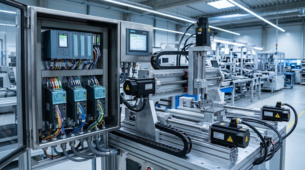
Modern industrial automation relies on Multi Axis Servo Control to achieve high-speed, synchronized machine movements without mechanical line shafts. High-performance packaging, printing, and CNC machinery demand tight position alignment between multiple servo drives. Consequently, engineers implement electronic gearing and camming within the PLC to handle these dynamic motion requirements smoothly.
What is Multi Axis Servo Control and Electronic Gearing?
Electronic gearing maintains a proportional speed or position relationship between master and slave motion axes. Electronic camming, by contrast, follows a predefined motion profile that maps the master position directly to the slave position.
For example, a geared slave maintains a constant speed ratio throughout a conveyor cycle. A cammed slave accelerates, dwells, and retracts at specific master positions during a pick-and-place operation.
Therefore, engineers select gearing for proportional motion and camming for complex, position-dependent movements. Many advanced machines combine both techniques to coordinate continuous production with precise material handling.
It covers the physical relationship between PLC hardware, servo drives, communication networks, and motion control configuration.
Engineers should follow standardized motion-control practices when developing coordinated servo applications. These practices help maintain consistent programming structures, improve compatibility, and simplify troubleshooting across different automation platforms. Moreover, engineers should verify that their PLC supports the required motion function blocks, electronic gearing, and synchronization features before commissioning the system.
Core Mechanical and Electrical Prerequisites for Multi Axis Servo Control
Reliable Multi Axis Servo Control synchronization depends on more than just a correct gear ratio. Engineers must carefully select compatible motors, feedback devices, servo drives, communication networks, and mechanical components. Otherwise, the system develops following errors, mechanical vibration, delayed responses, or inconsistent positioning.
1. High-Resolution Encoder Feedback in Multi Axis Servo Control
Each servo axis needs suitable position feedback to maintain accurate coordinated motion. Incremental and absolute encoders provide real-time position information, while the servo drive uses this feedback to regulate motor movement.
Higher encoder resolution improves position measurement, but resolution alone does not guarantee machine accuracy. Mechanical backlash, encoder quality, installation errors, electrical noise, and control-loop tuning also affect the final output.
For example, a precision cutting machine requires tighter position control than a general material-handling conveyor. Engineers should therefore select feedback devices according to the required positioning accuracy, operational speed, and ambient environment.
2. Fast and Deterministic Industrial Networks for Multi Axis Servo Control
Synchronized multi-axis systems require timely, low-jitter communication between the PLC controller and servo drives. Networks such as PROFINET IRT and EtherCAT support synchronized motion applications when engineers select compatible hardware and configure the network parameters correctly.
PROFINET IRT supports deterministic communication for demanding automation tasks. Similarly, EtherCAT supports distributed clock synchronization, which helps participating servo drives align their clock timing precisely.
However, engineers should not assume that a fast network automatically guarantees accurate motion. The controller cycle time, drive response speed, network configuration, synchronization settings, and application workload all influence overall system performance.
3. Matched Dynamic Response Across Multi Axis Servo Control Systems
Each axis must respond predictably to acceleration, deceleration, and dynamic load changes. If the master axis accelerates faster than the slave axis can follow, the slave develops a tracking error and breaks required synchronization.
Engineers must verify motor torque, load inertia, speed limits, acceleration capability, and drive sizing before commissioning the system. Moreover, they should evaluate the complete mechanical load rather than analyzing the motor alone.
4. Mechanical Alignment and Rigidity in Multi Axis Servo Control
Even an advanced motion controller cannot compensate for mechanical defects. Flexible couplings, loose mounting brackets, excessive gear backlash, axis misalignment, and unstable machine frames introduce severe vibration and positioning errors.
Consequently, engineers must inspect the mechanical transmission, verify coupling alignment, and secure all mounting hardware before tuning the servo axes. They should also confirm that drive belts, ball screws, gears, and bearings can handle peak operational loads throughout the machine cycle.
5. Controller and Drive Compatibility for Multi Axis Servo Control
The PLC or central motion controller must support the required coordinated motion functions, while the servo drives must support the chosen operating mode and fieldbus protocol.
Before writing PLC code, engineers should confirm axis configurations, encoder scaling, gear-ratio limits, synchronization commands, and fault-handling routines. This preparation eliminates commissioning errors and helps the machine maintain consistent, high-speed motion under changing factory conditions.
Step-by-Step Programming Logic for Multi Axis Servo Control
Reliable Multi Axis Servo Control starts with a clear motion sequence, correct axis configuration, and accurate position feedback. Engineers should define the master reference, configure each slave axis, establish the required gear ratio, and verify synchronization before running the machine at production speed. Moreover, the PLC program must handle motion faults, travel limits, and communication interruptions without creating unexpected movements.
Virtual Master vs. Real Master in Multi Axis Servo Control
A virtual master generates a reference position inside the motion controller, whereas a real master uses feedback from a physical motor or encoder. Engineers can configure a virtual axis in their PLC engineering software, define its velocity profile, and connect multiple slave axes to that reference. Consequently, the controller can coordinate several machine functions without requiring one physical motor to drive every movement.
A real master works well when the machine must follow an actual conveyor, rotating shaft, or production line. For example, a cutting axis can track conveyor movement and maintain accurate cutting positions as line speed changes. However, engineers must account for encoder scaling, gear ratios, and communication timing to prevent synchronization errors. The correct choice depends on the machine's mechanical design and production requirements.
Configuring Electronic Gearing Blocks in Multi Axis Servo Control
Motion function blocks provide a structured way to control electronic gearing. In PLCopen-based environments, MC_GearIn typically establishes a gearing relationship between a master and slave axis, while MC_GearOut disengages that relationship according to the controller's implementation. Engineers must verify the supported parameters and behavior in their specific PLC documentation before programming these commands.
For example, a PLC program can first enable both axes, check their readiness, and confirm that neither axis reports an active fault. The program can then issue MC_GearIn with the correct master reference, slave reference, and gear ratio. After the function block confirms successful engagement, the controller can monitor both axes throughout the production cycle. Similarly, MC_GearOut can disconnect the gearing relationship when the sequence requires independent slave movement.
However, disengaging electronic gearing does not automatically guarantee a safe stop. Engineers must define the slave axis's next motion, stopping behavior, and operating limits explicitly.
Troubleshooting Synchronization Errors in Multi Axis Servo Control
Synchronization problems can arise from incorrect gear ratios, excessive mechanical loads, communication delays, encoder faults, or unsuitable tuning parameters. Multi Axis Servo Control therefore requires engineers to monitor actual position, commanded position, velocity, and following error across every participating axis. These measurements help identify whether the problem originates in the control system, drive, feedback device, or mechanical transmission.
Managing Axis Lag and Following Errors in Multi Axis Servo Control
A following error occurs when the difference between an axis's commanded position and actual position exceeds the permitted tolerance. During acceleration, a slave motor may struggle to follow its reference because the load demands more torque than the drive and motor can deliver. As a result, the controller may report excessive position deviation and trigger a fault.
Engineers should first compare the master and slave position traces, inspect the following-error trend, and verify the electronic gear ratio. Next, they should examine motor loading, acceleration limits, encoder feedback, and network timing. If the mechanical system operates correctly, engineers can evaluate position-loop gain and velocity-loop tuning within the manufacturer's recommended limits.
Increasing gain without understanding the root cause can introduce vibration, noise, or instability. Therefore, engineers should make small adjustments, test the machine under controlled conditions, and compare the results at different speeds and loads.
Handling Emergency Stops and STO in Multi Axis Servo Control
An emergency stop during synchronized motion can disrupt the relationship between master and slave axes. For example, a conveyor may stop while a cutting axis continues moving, which can cause a collision or mechanical jam. Engineers must therefore design coordinated stopping behavior around the machine's hazards, inertia, load characteristics, and safety requirements.
Safe Torque Off (STO) prevents a servo drive from generating motor torque when the safety function activates. However, STO does not actively brake the motor or guarantee that moving machinery stops immediately. A high-inertia axis may continue coasting, so engineers must assess stopping distance and determine whether additional safety functions, mechanical brakes, or controlled stopping sequences are necessary.
For vertical axes, brake control deserves particular attention because gravity can move the load after the drive removes torque. Engineers should coordinate the brake, drive, and safety system according to the equipment manufacturer's instructions and the machine's risk assessment. They should also verify that an emergency stop cannot leave interconnected axes in a dangerous state.
Engineers should use the applicable standards and manufacturer documentation to validate the complete safety design rather than relying on PLC motion logic alone.
Ultimately, successful Multi Axis Servo Control combines accurate gearing, appropriate tuning, reliable feedback, and carefully engineered safety functions. Thorough commissioning and regular diagnostics help maintain synchronization, reduce downtime, and improve production consistency.
Advanced Electronic Cam Profiles in Multi Axis Servo Control
Electronic camming allows engineers to coordinate complex machine movements through a predefined relationship between master and slave positions. Unlike electronic gearing, which maintains a proportional motion relationship, an electronic cam profile can produce different slave positions at different points in the master cycle. Consequently, Multi Axis Servo Control can handle demanding applications such as packaging, synchronized cutting, labeling, and automated assembly.
Master Position Mapping and Interpolation in Multi Axis Servo Control
An electronic cam profile maps each master position to a corresponding slave position. Engineers define key points along the master cycle and assign the required slave positions to create the desired movement. The motion controller then interpolates between those points according to the selected cam profile and supported interpolation method.
For example, a packaging machine might keep a sealing head stationary while the film advances, move the head rapidly toward the package, maintain contact during sealing, and then return it to its starting position. A carefully designed cam profile coordinates these movements with the master axis, helping the machine maintain accurate timing at higher production speeds.
Moreover, engineers must consider acceleration, velocity, and jerk when designing cam profiles. Abrupt changes can increase vibration, mechanical stress, and following errors. Smooth transitions help the servo system track the reference while protecting mechanical components. Therefore, engineers should validate the complete motion profile against motor torque, travel limits, and the machine's operating cycle.
Commissioning and Validating Multi Axis Servo Control Systems
Commissioning begins with verifying motor direction, encoder scaling, axis limits, and communication status. Engineers should test each axis independently before engaging electronic gearing or camming. Next, they can run the coordinated sequence at a reduced speed and compare master and slave positions to confirm that each axis follows the intended motion relationship.
During live tests, engineers should monitor following errors, actual velocity, acceleration, drive status, and mechanical vibration. If the slave axis lags behind the master, they should investigate load inertia, torque limits, communication timing, and tuning parameters before increasing production speed. Similarly, engineers should check whether acceleration and deceleration profiles maintain smooth motion throughout the complete cycle.
After low-speed tests, engineers can increase speed gradually while monitoring performance under realistic operating loads. They should also verify fault recovery, stopping behavior, and safety functions before releasing the machine for production.
Conclusion: The Future of Multi Axis Servo Control
Multi Axis Servo Control gives industrial engineers greater flexibility when coordinating complex machinery. Electronic gearing maintains predictable relationships between axes, while electronic camming supports position-dependent movements that mechanical systems may struggle to achieve without additional hardware. Consequently, manufacturers can adapt motion sequences through software instead of repeatedly modifying mechanical transmissions.
Moreover, replacing traditional line shafts with electronic coordination can reduce mechanical coupling requirements, simplify machine modifications, and support modular production designs. However, these benefits depend on correct motor sizing, suitable feedback devices, reliable communication, and thorough commissioning. Engineers must also integrate appropriate safety functions and validate the complete machine against its operating risks.
Ultimately, successful multi-axis automation requires more than connecting several servo motors to one PLC. Engineers must combine sound mechanical design, precise motion programming, effective tuning, and validated safety measures to achieve reliable performance. When engineers master electronic gearing and camming, they build more accurate, adaptable, and scalable motion systems for modern industrial production.