Modern industrial automation systems require precise motion control, reliable communication, and consistent machine performance. For these reasons, manufacturers often combine programmable logic controllers (PLCs) with servo motors to control positioning, speed, and acceleration in automated equipment. This combination supports applications such as packaging machines, CNC equipment, robotic systems, conveyor mechanisms, and automated assembly lines.
However, successful integration requires more than connecting a motor to a controller. Engineers must select a compatible servo drive, establish the correct communication method, configure motion parameters, and verify feedback signals. In addition, they must consider electrical noise, mechanical loads, stopping distances, and machine safety before operating the system.
PLC and servo motor integration allows a PLC to coordinate machine sequences while a servo drive manages the motor's electrical operation and motion response. When engineers configure these components correctly, the system can achieve repeatable positioning, smooth acceleration, and reliable synchronization between machine axes.
This guide explains the system architecture, essential components, wiring methods, communication options, and practical setup considerations involved in integrating a PLC with a servo motor.
Understanding PLC and Servo Motor Integration
A PLC and servo motor perform different but complementary functions. The PLC executes the machine-control program, processes sensor inputs, and determines when an axis should move. Meanwhile, the servo drive converts the PLC's commands into controlled electrical power for the motor.
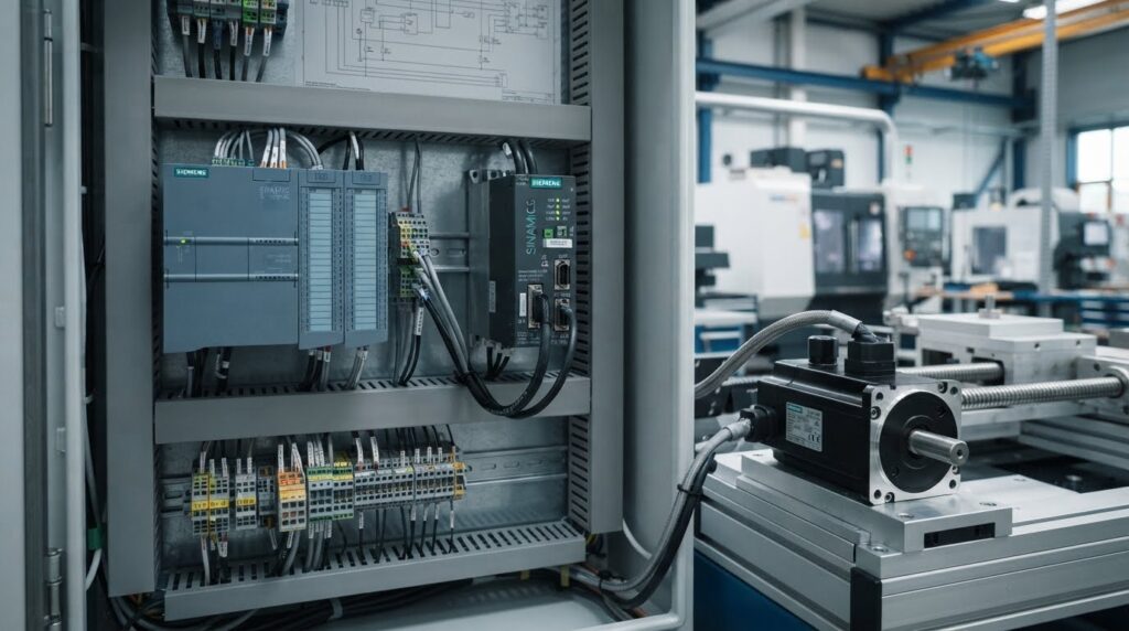
A typical system contains three main control elements: the PLC, servo drive, and servo motor. An encoder or another supported feedback device measures the motor's actual movement and returns position or speed information to the drive.
1. Programmable Logic Controller (PLC)
The PLC acts as the main machine controller. It reads input signals from sensors, switches, and other devices before executing its programmed logic. Based on these inputs, it issues motion commands and coordinates the servo axis with the rest of the machine.
For example, a packaging machine may use a photoelectric sensor to detect a product. The PLC then commands the servo-driven mechanism to move a cutting blade to the required position. Once the movement finishes, the PLC checks the completion status before allowing the next production step.
The PLC must support the motion-control method required by the application. Basic PLC models may provide digital outputs for simple pulse-based commands, whereas advanced motion controllers can support coordinated axes, electronic gearing, cam profiles, and synchronized motion.
Therefore, engineers should check the controller's motion instructions, output frequency, communication interfaces, and axis capacity before selecting the hardware.
2. Servo Drive
The servo drive serves as the interface between the PLC and the motor. It receives motion references, compares the requested movement with feedback information, and adjusts the motor's electrical power accordingly.
Most industrial servo drives use closed-loop control. Depending on the drive architecture, internal control loops regulate current or torque, velocity, and position. The drive continuously processes feedback to reduce the difference between the commanded response and the measured motor behavior.
For instance, if a machine requires the motor to rotate through a precise angle, the drive uses the selected command mode and feedback information to control that movement. If the motor encounters an unexpected load, the control system can adjust its output within configured limits.
However, the drive cannot overcome every mechanical limitation. An oversized load, incorrect tuning, excessive inertia, or insufficient motor torque can still cause tracking errors, vibration, or alarms.
3. Servo Motor and Feedback Encoder
The servo motor converts electrical energy into controlled mechanical motion. Industrial servo motors commonly use permanent-magnet synchronous designs because they provide accurate speed control, strong dynamic response, and high torque relative to their size.
An encoder measures the motor shaft's position and movement. Depending on the system, the encoder may provide incremental or absolute position information. The servo drive uses this feedback to regulate the motor and determine whether it follows the commanded motion.
Importantly, the encoder connection usually runs to the servo drive rather than directly to the PLC. Some systems also transmit actual position, velocity, and diagnostic information to the PLC through a supported communication interface.
This arrangement separates fast motor regulation from higher-level machine sequencing. Consequently, the drive can manage the motor's response while the PLC coordinates the complete production process.
How a PLC Controls a Servo Motor
Understanding the control sequence helps engineers troubleshoot integration problems and select the appropriate hardware. Although the exact process varies by manufacturer, a typical system follows several stages.
First, the PLC checks operating conditions, including emergency-stop status, machine interlocks, limit switches, and drive readiness. Next, it sends an enable request or motion command through the configured interface. The servo drive then verifies its own operating conditions and accepts the command when all required conditions are satisfied.
After the drive accepts the command, it controls the motor according to the selected operating mode. The encoder supplies feedback, allowing the drive to regulate movement. Finally, the PLC monitors signals such as in-position, motion complete, drive ready, and fault status before advancing the machine sequence.
For example, an automated positioning table may need to move a component by 150 mm. The PLC requests the target position, velocity, and acceleration through the supported motion interface. The drive executes the movement, while the control system checks the axis status. Once the axis reaches the configured completion conditions, the PLC permits the next operation.
Nevertheless, engineers should not assume that a single completion signal proves every positioning requirement has been met. They must review the drive's status definitions, position tolerance, settling behavior, and motion instruction semantics.
PLC and Servo Motor Wiring Methods
The correct wiring method depends on the PLC model, servo drive, application requirements, and available communication interfaces. Before connecting any equipment, engineers should consult the manuals for the exact hardware models.
Pulse and Direction Wiring
Pulse-and-direction control is a common method for connecting a PLC to a compatible servo drive. In this arrangement, the PLC sends a series of pulses to represent commanded movement, while a separate direction signal indicates the required direction of travel.
The drive interprets the pulse frequency as a movement-rate reference and the pulse count as a movement increment, subject to its electronic gearing and configuration. For example, a higher pulse frequency generally commands faster movement within the configured limits, while a greater pulse count requests a larger displacement.
However, engineers must verify the PLC's output type, maximum pulse frequency, electrical interface, and wiring requirements. Some systems use differential line-driver signals, whereas others support specific single-ended interfaces. These arrangements are not automatically interchangeable.
In addition, the PLC's pulse output must provide sufficient resolution for the required positioning accuracy. Engineers should configure the electronic gear ratio carefully and account for encoder resolution, mechanical transmission ratios, and units of movement.
Analog Speed or Torque Commands
The analog reference also does not replace the drive's internal feedback regulation. The drive continues to control the motor according to its configured operating mode and feedback architecture.
For example, a drive configured for a specified bipolar voltage range may interpret positive and negative reference values as opposite directions or torque commands, depending on its settings. Engineers must confirm the drive's scaling, polarity, signal range, and operating mode before applying the reference.
Analog control can suit applications that need a continuous reference rather than a digital position command. Nevertheless, electrical noise, grounding differences, signal resolution, and calibration errors can affect performance. Therefore, engineers should use the manufacturer's recommended shielded wiring and grounding arrangement.
The analog reference also does not replace the drive's internal feedback regulation. The drive continues to control the motor according to its configured operating mode and feedback architecture.
PLC and Servo Motor Integration Through Industrial Communication Networks
Modern PLC and Servo Motor Integration relies on reliable communication between the programmable logic controller (PLC) and the servo drive. The communication method affects response time, positioning accuracy, synchronization, and system diagnostics. Therefore, engineers should select a control method that matches the machine's motion requirements.
Pulse-and-direction signals provide a straightforward solution for basic positioning applications. The PLC sends pulses to represent movement, while the direction signal determines the direction of rotation. However, engineers must configure pulse scaling correctly to ensure that the commanded movement matches the required distance.
For advanced PLC and Servo Motor Integration, industrial networks such as EtherCAT and PROFINET offer coordinated communication between controllers and servo drives. EtherCAT supports fast, synchronized data exchange for demanding motion-control applications. PROFINET provides industrial communication options for systems that need reliable controller-to-drive coordination.
Modbus and analog signals can also support simpler speed or torque-control applications. Nevertheless, these methods may not provide the synchronization features required by complex multi-axis machines. Before selecting a protocol, engineers should evaluate update times, compatibility, diagnostic features, and the number of axes involved.
Drive Configuration for PLC and Servo Motor Integration
Correct drive configuration is essential for successful PLC and Servo Motor Integration. Engineers must first select the required operating mode, such as position, speed, or torque control. Each mode determines how the drive interprets commands from the PLC and controls motor movement.
Next, enter the motor parameters according to the manufacturer's documentation. These settings may include rated current, rated voltage, encoder resolution, maximum speed, and motor identification data. Incorrect parameters can trigger alarms, reduce performance, or cause the motor to operate outside its intended limits.
Command scaling is another important part of PLC and Servo Motor Integration. For pulse-based control, the engineer must establish the relationship between input pulses and motor movement. For network-based control, the PLC axis configuration and drive command units must use compatible scaling.
Electronic gearing may be required when the application needs a defined relationship between the command position and actual motor movement. Engineers should also configure acceleration, deceleration, travel limits, and appropriate torque limits. These settings help prevent abrupt movements and reduce unnecessary mechanical stress.
Before running the machine at full speed, verify the motor direction and test movement using a low-speed command. Confirm that actual movement matches the requested direction and distance. Only increase operating limits after the system responds correctly and consistently.
PLC and Servo Motor Integration for Accurate Positioning
Accurate positioning depends on coordination between PLC logic, servo-drive control, and encoder feedback. In a typical PLC and Servo Motor Integration setup, the PLC determines the target position while the servo drive regulates motor current and movement using feedback from the encoder.
Consider a packaging machine that moves a conveyor by a fixed distance before filling a container. The PLC checks the sensor inputs, confirms that the drive is ready, and issues the positioning command. The drive then moves the motor toward the target and reports its status to the PLC.
Reliable PLC and Servo Motor Integration requires more than sending a motion command. The PLC should monitor drive-ready status, motion-complete signals, in-position status, and fault conditions. It should also use suitable timeouts to detect movements that take longer than expected.
For example, if the drive fails to reach the target position, the PLC should stop the sequence or enter a defined fault-handling routine. Continuing the production cycle without confirming the movement could cause incorrect filling, material waste, or mechanical collisions.
Multi-axis applications require additional coordination. Electronic gearing, camming, and synchronized motion functions can maintain the required relationship between axes. These features are useful in printing, cutting, labeling, and material-handling systems where timing and position must remain consistent.
Commissioning PLC and Servo Motor Integration
Commissioning verifies that the electrical installation, PLC program, communication settings, and servo-drive configuration operate together correctly. A structured commissioning process reduces the risk of unexpected movement and helps identify faults before production begins.
First, inspect the power connections, protective grounding, cable shielding, communication wiring, and motor connections. Confirm that the motor and drive ratings match the application. Also verify that emergency stops, guards, and other required safety functions have been installed and tested according to the machine's safety requirements.
Next, power up the system using the manufacturer's recommended procedure. Check the drive display for alarms and confirm that the PLC can communicate with the drive. Verify that status signals, command values, and feedback data appear as expected.
During initial PLC and Servo Motor Integration testing, use a low speed and a limited travel distance. Check the motor's direction of rotation and compare the commanded position with the actual position. If the results do not match, stop the test and investigate the configuration before continuing.
After basic movement succeeds, test acceleration, deceleration, repeatability, and operation under the expected load. Monitor drive current, following error, and relevant diagnostic values where available. Record the final parameters so technicians can restore the configuration after maintenance or component replacement.
Common PLC and Servo Motor Integration Problems
Even a correctly designed system can develop problems because of wiring errors, incorrect parameters, mechanical resistance, or communication interruptions. Effective PLC and Servo Motor Integration troubleshooting begins with diagnostic evidence rather than random parameter changes.
The servo motor does not move. Check the drive-ready signal, enable conditions, active alarms, operating mode, and command values. For network-based systems, verify communication status and confirm that the PLC has enabled the correct axis.
The motor moves in the wrong direction. Review the direction settings, coordinate system, and command configuration. Confirm that the mechanical arrangement matches the intended movement. Follow the manufacturer's procedure before changing any motor or encoder wiring.
Positioning accuracy is poor. Incorrect scaling, mechanical backlash, loose couplings, excessive load, or unsuitable tuning can cause positioning errors. Compare the target position with encoder feedback, then inspect the mechanical system and configuration.
The motor vibrates or produces excessive noise. Possible causes include incorrect servo gains, mechanical resonance, poor mounting, and load inertia mismatch. Inspect the installation first. If the drive supports automatic tuning or resonance filters, use these features according to the manufacturer's instructions.
Communication faults interrupt operation. Inspect network cables, connectors, device addresses, configuration settings, and diagnostic messages. Check whether faults occur continuously or only during heavy machine activity. In network-based PLC and Servo Motor Integration, communication timing must suit the application's motion requirements.
Safety and Maintenance for PLC and Servo Motor Integration
Safety must remain a priority throughout the design, installation, and maintenance of PLC and Servo Motor Integration systems. Emergency stops, protective guards, limit switches, and safety-rated functions must follow the machine's risk assessment and applicable standards. A standard PLC software command should not replace a required safety-rated function.
Before inspecting electrical connections or mechanical components, isolate the equipment and follow the site's lockout/tagout procedure. Servo drives and DC bus capacitors may retain dangerous electrical energy after the supply has been disconnected. Follow the manufacturer's discharge instructions and verify a safe condition before starting work.
Routine maintenance helps preserve system reliability. Inspect connectors, cooling fans, filters, cable shielding, motor mounting, and mechanical couplings at suitable intervals. Review drive alarms and operating trends to identify recurring problems before they cause unplanned downtime.
For dependable PLC and Servo Motor Integration, maintain backups of PLC programs, servo-drive parameters, network configurations, and commissioning records. Documenting changes also helps technicians identify configuration differences when troubleshooting recurring faults.
Frequently Asked Questions
What is PLC and Servo Motor Integration?
PLC and Servo Motor Integration connects a programmable logic controller with a servo drive and motor to control position, speed, and torque. The PLC manages machine sequences, while the servo drive controls motor movement using feedback from an encoder.
Which communication methods are used for PLC and Servo Motor Integration?
Common methods include pulse-and-direction signals, analog signals, Modbus, EtherCAT, and PROFINET. The right option depends on the required positioning accuracy, response time, synchronization, and compatibility between the PLC and servo drive.
How do you troubleshoot PLC and Servo Motor Integration problems?
Check drive alarms, enable signals, wiring, communication status, motor parameters, and encoder feedback. If positioning is inaccurate or the motor vibrates, inspect mechanical components and configuration before adjusting servo tuning parameters.
What should you check before commissioning PLC and Servo Motor Integration?
Verify electrical connections, grounding, motor and drive ratings, communication settings, command scaling, travel limits, and safety functions. Begin with low-speed movement and limited travel, then test positioning accuracy and performance under the expected load.
Conclusion
Successful PLC and Servo Motor Integration depends on selecting a suitable control method, configuring the servo drive correctly, validating encoder feedback, and testing every motion sequence. Engineers should match the communication system to the application's positioning accuracy, response time, and synchronization requirements.
A structured commissioning process helps identify wiring mistakes, incorrect settings, and mechanical issues before full production begins. Clear PLC logic and effective fault handling also improve machine diagnostics and reduce unnecessary downtime.
By combining compatible hardware, correct drive configuration, reliable feedback, appropriate safety measures, and planned maintenance, engineers can achieve accurate movement and consistent performance in industrial automation systems.

Pingback: Multi Axis Servo Control: PLC Electronic Gearing Guide