Servo motor tuning plays a critical role in achieving accurate, stable, and responsive motion in industrial automation systems. Although a servo motor may operate correctly after installation, poor tuning can still cause vibration, overshoot, delayed positioning, and inconsistent machine performance. These problems become particularly important in CNC machines, robotic arms, packaging equipment, and automated assembly lines, where even small positioning errors can affect product quality and production speed. Therefore, engineers must understand how the servo drive processes feedback, adjusts motor commands, and responds to changing mechanical loads. Effective servo motor tuning helps the complete motion control system follow its commanded movement with greater accuracy while maintaining stability under real operating conditions.
However, tuning does not simply mean increasing a few drive parameters until the motor responds faster. Every adjustment affects the relationship between responsiveness, stability, noise, and mechanical stress. For example, excessive gain may produce a quick response but also introduce oscillation, while insufficient gain may cause sluggish movement and positioning errors. Consequently, engineers must evaluate the motor, drive, encoder, mechanical transmission, and application requirements together. By understanding these relationships, technicians can improve motion performance without creating unnecessary vibration, overheating, or premature equipment wear.
What Is Servo Motor Tuning?
Servo motor tuning is the process of adjusting a servo drive's control parameters so that the motor follows commanded position, speed, or torque with the required accuracy and stability. The drive continuously compares the commanded motion with feedback from an encoder or another supported sensor. It then calculates the difference between the requested response and the measured response, known as the tracking error. Based on this error, the controller adjusts its output to bring the motor closer to the target. Proper tuning allows the system to correct errors quickly without producing excessive oscillation or unstable movement.
In practical applications, the ideal tuning settings depend on the machine's mechanical characteristics and operating conditions. A lightweight robotic joint may require a different response from a heavy conveyor axis or a CNC machine with a long ball screw. Similarly, a machine that performs rapid point-to-point movements may need different settings from equipment that follows a smooth, continuous motion profile. Therefore, engineers should define measurable performance requirements before changing parameters. These requirements may include settling time, allowable positioning error, maximum overshoot, vibration levels, and the ability to maintain stable operation across the intended speed and load range.
Understanding the Servo Control Loops
Most industrial servo systems use a cascaded control structure with current or torque control inside the velocity loop and the velocity loop inside the position loop. Each loop performs a different task, but their coordinated operation determines the overall response. Understanding this structure is essential because an adjustment to one loop can influence the behaviour of the others.
Current and Torque Control Loop
The current control loop operates close to the motor's electrical system and regulates the motor current according to the drive's torque command. In many permanent-magnet AC servo motors, torque relates approximately linearly to torque-producing current within the motor's rated operating range. As a result, the drive uses current regulation to produce the torque required for acceleration, deceleration, and load compensation. A well-functioning current loop responds quickly to torque demands while maintaining controlled current behaviour.
Nevertheless, engineers should not adjust current-loop parameters casually. The motor's electrical characteristics, drive hardware, current sensors, and manufacturer-defined control algorithms all influence this loop. Incorrect settings may introduce current oscillation, excessive electrical noise, or unstable torque production. For this reason, technicians should normally retain the manufacturer's recommended current-loop configuration unless the drive documentation specifically permits adjustment and suitable test procedures are available.
Velocity Control Loop
The velocity loop regulates motor speed by comparing the commanded velocity with the speed measured or estimated from feedback. It then adjusts the torque command to reduce the difference. This loop plays an important role during acceleration, deceleration, sudden load changes, and movements that require consistent speed. If the velocity response lacks sufficient control, the motor may struggle to maintain its commanded speed or may react poorly when the mechanical load changes.
During servo motor tuning, engineers often evaluate velocity-loop proportional gain and integral gain, where the drive exposes these parameters. Proportional gain increases the controller's response to the current speed error, while integral gain accumulates error over time to help eliminate persistent differences. However, excessive proportional gain can amplify mechanical resonance or cause oscillation, and excessive integral action can produce overshoot or prolonged recovery. Therefore, technicians must balance response speed with stability and follow the drive manufacturer's tuning procedure.
Position Control Loop
The position loop compares the target position with the actual position and calculates the correction required to reduce the tracking error. The controller typically converts this position error into a velocity command for the inner loop. Its behaviour strongly influences positioning accuracy, settling time, and overshoot during point-to-point movements. For instance, a robotic axis that stops repeatedly at precise assembly locations needs a controlled response that reaches the target quickly without continuing to oscillate around it.
Increasing position-loop gain may reduce position error and improve stiffness, but excessive gain can create instability when the machine's mechanics cannot support the requested response. Furthermore, backlash, flexible couplings, belt elasticity, and structural resonance can limit achievable accuracy regardless of the controller settings. Engineers should therefore assess the mechanical system before demanding a more aggressive position response. A stable position loop must work with the inner control loops rather than forcing them to compensate for mechanical problems they cannot reliably correct.
Proportional Gain and Integral Gain Adjustment
Proportional and integral gains determine how a servo system responds to errors and changing loads. During servo motor tuning, engineers must understand both settings before making adjustments. Proportional gain controls the strength of the immediate correction. Higher gain can improve responsiveness, but excessive values may cause vibration, noise, and instability. In contrast, low gain can produce sluggish movement and reduce performance during rapid acceleration or precise positioning.
Integral gain helps eliminate persistent errors by accumulating the difference between commanded and measured responses. It can improve speed regulation under sustained loads. However, excessive integral action may cause overshoot, oscillation, or slow recovery after disturbances. Some drives include anti-windup protection and integral limits to control these effects. Engineers should check the manufacturer's documentation before adjusting these features, as their operation varies between drive models.
Start servo motor tuning with the manufacturer's recommended settings and a controlled test movement. Adjust one parameter at a time and record the original values. After each change, compare tracking error, settling time, vibration, and motor current under consistent conditions. This method helps identify effective adjustments and avoid unwanted changes in system performance.
Auto-Tuning Versus Manual Servo Motor Tuning
Automatic tuning helps a servo drive estimate mechanical characteristics and configure suitable control parameters. Depending on the model, it may use test movements or measured responses. Some drives support stationary, low-speed, and dynamic tuning routines. This feature can reduce commissioning time, especially when configuring multiple axes with different loads.
However, automatic tuning may not deliver optimal results under every operating condition. Changes in payload, axis position, and speed can affect machine response. Flexible couplings and long transmissions may also create resonances that basic tuning routines cannot fully detect. Therefore, engineers should test the settings across the machine's intended operating range to confirm stable and reliable performance.
Manual servo motor tuning gives engineers greater control over system response. It helps address excessive overshoot, resonance, and slow settling after automatic tuning. However, successful adjustments require knowledge of drive parameters and mechanical limitations. Combining automatic identification with careful testing and small, controlled changes often delivers more reliable results.
Understanding Overshoot, Settling Time, and Tracking Error
Three measurements help engineers evaluate servo performance: overshoot, settling time, and tracking error. Each reveals a different aspect of the response. Overshoot occurs when the measured position passes beyond the target before returning towards the commanded value. Settling time describes how long the response takes to enter and remain within a defined tolerance band around the target. Tracking error represents the difference between the commanded and actual position during movement.
These measurements should be interpreted together. For example, a machine may reach its target quickly but exhibit significant overshoot. Another axis may avoid overshoot yet take too long to settle. A third may follow a smooth trajectory but develop excessive error during acceleration. Consequently, engineers should select performance limits based on the process requirements rather than judging the system by movement speed alone.
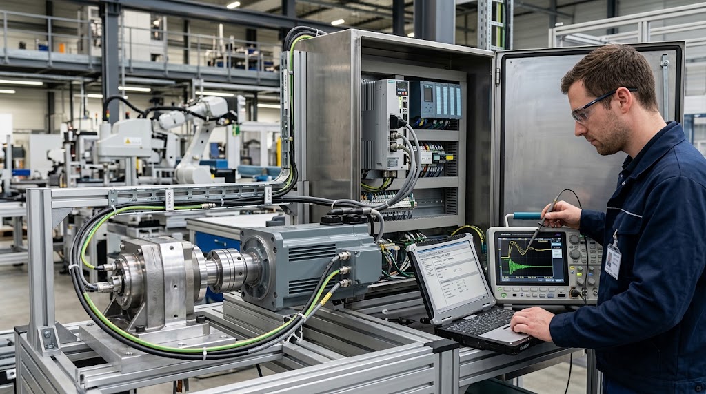
During servo motor tuning, the drive's trace or oscilloscope function can reveal these behaviours. Engineers can record commanded position, actual position, velocity, torque-producing current, and following error when the drive supports those signals. They should use a repeatable motion profile and maintain the same load conditions during comparisons. This process helps distinguish a genuine improvement from a change caused by different test conditions.
Vibration and Mechanical Resonance Control
Vibration can significantly affect servo system accuracy and stability. Common causes include mechanical resonance, loose mounts, misaligned couplings, excessive gain, and poorly configured motion profiles. When the control bandwidth interacts with the machine's natural resonance, unwanted oscillations may occur. Therefore, engineers should identify the root cause before adjusting gain settings, as excessive adjustments can worsen vibration and reduce system performance.
Engineers should inspect mounting bolts, couplings, bearings, backlash, and structural rigidity. They should also identify when vibration occurs, such as during acceleration, at specific speeds, or near certain positions. These observations help pinpoint the cause. For example, vibration at a particular speed may indicate mechanical resonance, while unstable tracking with unusual noise may suggest a control-related issue.
Servo drives often include notch filters, low-pass filters, and resonance suppression tools to control unwanted vibration. A notch filter targets a specific frequency, whereas a low-pass filter reduces high-frequency signals. Although these features can improve stability, excessive filtering may slow response and weaken disturbance rejection. Engineers should analyse the vibration, follow manufacturer guidelines, and test system performance after each adjustment.
Load Inertia and Mechanical Matching
Load inertia affects how readily a servo system accelerates and decelerates. A motor driving a lightweight mechanism behaves differently from the same motor connected to a heavy rotary table or a large transmission assembly. When the reflected load inertia becomes high relative to the motor's rotor inertia, the system may require more torque and careful control adjustment. Poor mechanical matching can also limit achievable acceleration and make aggressive tuning difficult.
The relevant comparison depends on the complete transmission system. Gearboxes, belts, pulleys, ball screws, and couplings can change the load inertia reflected to the motor shaft. Engineers must account for the transmission ratio and the mechanical arrangement rather than comparing the raw inertia values without conversion. They should also consider friction, gravitational forces, acceleration requirements, and the load's changing position.
A high inertia ratio does not always prevent reliable operation, as some servo drives offer advanced identification and compensation features. However, engineers must check equipment ratings and manufacturer guidelines before commissioning. If the load exceeds practical limits, a suitable gearbox, a larger motor, or an improved transmission design may deliver better results than aggressive tuning.
Advanced Servo Motor Tuning Through Real Industrial Examples
Practical applications reveal how engineers translate tuning principles into reliable machine performance. The correct approach depends on the process, mechanical design, production targets, and acceptable positioning error. Therefore, engineers should evaluate the complete machine rather than adjust parameters in isolation.
Example 1: Improving Positioning Accuracy in a CNC Machine
Consider a CNC machine that repeatedly stops at a commanded position but occasionally produces dimensional variations. The servo drive reports acceptable positioning under light movement, yet the error increases during rapid direction changes. This behaviour suggests that the engineer should investigate dynamic performance rather than assume the encoder has failed.
A useful diagnostic process begins with a repeatable test program. The engineer records commanded position, actual position, following error, and motor current during acceleration, steady movement, and deceleration. If the error increases mainly during acceleration, the engineer checks the available torque, acceleration settings, mechanical friction, and transmission condition. If the error continues after the axis reaches its target, the engineer investigates settling behaviour and possible mechanical resonance.
The next step in servo motor tuning involves testing suitable drive settings within manufacturer limits. The engineer may adjust permitted controller gains or motion-profile parameters, changing one variable at a time. After each change, the machine repeats the same movement under comparable conditions. The engineer then compares positioning error, settling time, vibration, and repeatability. This evidence-based approach helps identify improvements without sacrificing stability. Finally, the engineer verifies dimensional accuracy using the machine's approved measurement procedure rather than relying solely on the drive's feedback display.
Example 2: Reducing Vibration in a Packaging Machine
A packaging machine may use a servo axis to move film, position containers, or operate a cutting mechanism. Suppose the axis develops vibration during rapid acceleration. The vibration increases production noise and may affect registration accuracy. Increasing the controller gain might initially appear attractive because the machine needs a quick response. However, that adjustment could amplify an existing mechanical resonance.
The engineer first determines when the vibration occurs. If it appears only within a narrow speed range, the mechanical system may have a speed-dependent resonance. If it occurs immediately after every abrupt command, the motion profile or control response may contribute to the problem. The engineer also inspects mounting hardware, couplings, belts, bearings, and other mechanical components.
After correcting mechanical defects, the engineer evaluates the drive's diagnostic traces and supported resonance suppression features. A suitable filter may reduce a specific resonant response, while a smoother acceleration profile may reduce excitation of the mechanism. These solutions address different causes, so the engineer should not treat them as interchangeable. Following servo motor tuning, the machine must complete repeated cycles at representative production speeds. The final verification should include registration accuracy, vibration, cycle consistency, and motor temperature.
Example 3: Stabilising a Servo Axis With Changing Loads
Industrial robots, automated assembly systems, and material-handling machines often experience changing loads. A robotic joint may carry a tool during one operation and a heavier workpiece during another. These changes affect inertia, acceleration demand, and the torque needed to maintain the commanded motion.
Suppose a robotic axis performs accurately without a workpiece but develops excessive following error when carrying a heavier payload. The engineer first checks whether the actual load remains within the robot's rated capacity. Next, the engineer reviews payload configuration, centre of gravity, acceleration limits, and the manufacturer's recommended motion settings. Incorrect payload information can cause the controller to operate with an unsuitable model of the machine.
Where the system supports load-dependent compensation or gain scheduling, the engineer may evaluate these functions according to the manufacturer's instructions. Otherwise, the engineer can assess whether a more conservative motion profile provides sufficient performance. Testing should cover the lightest and heaviest permitted loads, along with representative operating positions. This procedure helps ensure that the selected configuration remains stable across the intended working range instead of performing well under only one test condition.
Using Servo Drive Diagnostic Tools Effectively
Modern servo drives often provide monitoring functions that help engineers identify faults and evaluate dynamic response. Depending on the model, these functions may include internal trace recording, alarm history, encoder monitoring, frequency analysis, and measurements of current or torque demand. Engineers should understand what each signal represents before drawing conclusions from it.
For example, a commanded position trace shows the requested movement, while an actual position trace shows the feedback response. Comparing these signals reveals when the axis begins to lag behind its command. A velocity trace can help identify speed fluctuations, and a current trace may reveal changing torque demand. However, current alone does not prove that the motor has reached its torque limit. Engineers must also consider drive ratings, scaling, operating conditions, and the manufacturer's diagnostic definitions.
Sampling rate also matters when investigating rapid oscillations. A trace that records data too slowly may hide short-duration events or misrepresent the waveform. Therefore, engineers should select suitable recording settings and use the drive's supported analysis functions. They should preserve useful traces before and after an adjustment. Clear records make comparisons more reliable and help maintenance teams understand why a particular configuration was selected.
Commissioning and Performance Verification
A successful commissioning procedure confirms that the servo system performs safely and consistently under its intended operating conditions. Engineers should verify motor and drive compatibility, correct feedback configuration, mechanical installation, protective grounding, and manufacturer-specified wiring requirements. They must also confirm that emergency stops, safety interlocks, guarding, and other required protective functions operate correctly.
Before applying motion, technicians should inspect parameter settings and check the manufacturer's startup procedure. Initial movements should use an approved commissioning mode and conservative operating limits. The engineer should confirm direction of rotation, feedback polarity, travel limits, and basic command response before progressing to more demanding tests. Any unexpected movement, abnormal noise, or drive alarm requires investigation before commissioning continues.
Once basic operation is stable, the engineer can evaluate the axis at progressively more representative speeds and loads. Testing should cover acceleration, deceleration, repeated positioning, expected payload changes, and the normal operating range. During servo motor tuning, engineers should record the final parameters alongside measured performance and any relevant limitations. They should also retain a backup of the validated configuration when the drive supports parameter export. This documentation simplifies future maintenance and helps prevent unverified changes from undermining reliable operation.
Common Servo Tuning Mistakes and How to Avoid Them
One common mistake involves changing several parameters simultaneously. Although the machine may appear to improve, the engineer cannot easily identify which change produced the result. A more reliable method changes one parameter at a time and repeats the same test. This discipline improves traceability and makes unexpected behaviour easier to diagnose.
Another mistake involves treating every vibration problem as a gain-setting issue. Mechanical looseness, damaged bearings, misalignment, poor cable installation, and resonance can produce similar symptoms. Engineers should inspect the physical system and review diagnostic evidence before making control adjustments. Likewise, aggressive filtering may conceal a symptom without correcting its underlying cause.
Engineers should also avoid copying tuning values from another machine simply because both systems use similar motors. Different payloads, transmission ratios, mounting structures, and drive configurations can produce substantially different responses. Even identical machines may behave differently after mechanical modifications or component replacement. Consequently, validated manufacturer procedures and measurements from the actual installation should guide the final settings.
Technical Resources for Further Learning
Engineers can develop advanced motion-control skills by studying servo drive manuals, motor specifications, and industrial control-system principles. These resources explain tuning parameters, feedback signals, diagnostic functions, and manufacturer-approved commissioning procedures. Understanding the exact drive model is particularly important because parameter names, adjustment methods, and supported features vary between manufacturers.
Practical testing also plays an essential role in technical learning. Engineers should compare commanded and actual motion, examine diagnostic traces, and record performance under repeatable operating conditions. By combining theoretical knowledge with measured results, they can identify control limitations, diagnose faults, and improve machine performance more reliably. Always follow the equipment manufacturer's instructions and applicable industrial safety requirements.
Conclusion
Reliable servo performance requires a balanced approach to control settings, mechanical condition, diagnostics, and application requirements. Engineers achieve better results when they measure actual machine behaviour instead of relying on assumptions or aggressive parameter changes. They should also validate the final configuration across representative loads, speeds, and operating cycles.
Ultimately, effective servo motor tuning improves motion quality only when the controller and mechanical system work together. Careful commissioning, repeatable testing, documented adjustments, and manufacturer-approved procedures provide a stronger foundation for accurate positioning, stable movement, and dependable industrial operation.

Pingback: PLC and Servo Motor Integration: Wiring and Setup
Pingback: Multi Axis Servo Control: PLC Electronic Gearing Guide