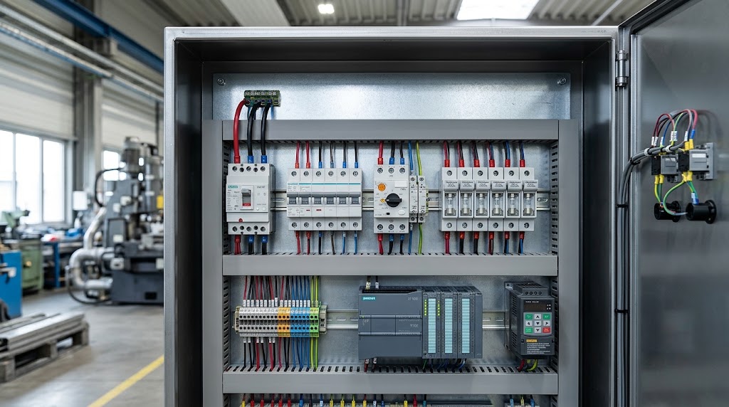
Control Panel Circuit Protection plays an essential role in modern factories because automated production depends on stable power distribution and reliable electrical equipment. As a result, engineers must protect control panels against electrical faults that can damage components, interrupt production, and create safety risks. Therefore, selecting suitable protective devices helps maintain reliable operations and supports safer industrial environments.
Why Control Panel Circuit Protection Matters
Control panel circuit protection uses electrical devices to detect or interrupt excessive current and dangerous fault conditions. These devices help protect cables, motors, control equipment, and other components from electrical damage. However, engineers must select each device according to the circuit requirements, load characteristics, and available fault current.
Overcurrent and Overloads
Overcurrent occurs when a circuit carries more current than its intended operating level. For example, a motor may draw excessive current when a machine experiences mechanical resistance or operates beyond its designed load. Consequently, cables and terminals can overheat, while prolonged overloads may damage insulation and connected equipment.
Engineers should therefore match protective-device ratings with conductor sizes and equipment specifications. In addition, they must consider the load's normal starting current to prevent unnecessary trips.
Short Circuits
A short circuit occurs when current follows an unintended low-resistance path between conductors or between a conductor and earth. As a result, fault current can rise rapidly and damage cables, contactors, power supplies, and other electrical components.
However, not every protective device can safely interrupt every fault level. Engineers must check the prospective short-circuit current and choose a device with an appropriate breaking capacity. Furthermore, proper coordination helps isolate faults while limiting disruption to unaffected circuits.
Thermal and Arc Flash Risks
Electrical faults can produce intense heat, sparks, and dangerous arcs. Consequently, workers may face serious injury risks, and nearby equipment may suffer extensive damage. Loose connections, damaged insulation, contamination, and poor maintenance can also increase these hazards.
Properly selected protection helps interrupt certain fault conditions quickly; however, it cannot eliminate every thermal or arc-flash risk. Therefore, engineers should also use suitable enclosures, safe working procedures, correct installation practices, and regular inspections.
Key Benefits for Industrial Control Panel Circuit Protection
A well-designed protection system improves equipment reliability and helps factories maintain consistent production. Furthermore, it allows engineers to manage electrical risks and simplify maintenance.
Protecting PLCs, VFDs, and Control Equipment
Industrial panels often contain programmable logic controllers (PLCs), variable frequency drives (VFDs), human-machine interfaces (HMIs), and 24V DC power supplies. These components support machine control and communication; therefore, faults in their supply circuits can affect the wider automation system.
For example, a correctly selected branch-circuit protective device can isolate a faulty circuit without unnecessarily interrupting every connected system. In addition, engineers should follow manufacturer instructions and consider the protection requirements of sensitive electronic equipment.
Reducing Unplanned Downtime
Electrical faults can stop machines, delay production, and increase maintenance costs. However, engineers can reduce these disruptions by selecting suitable protective devices and coordinating them with the rest of the electrical system.
Clear circuit labels and organized panel layouts also help technicians locate faults more efficiently. Consequently, maintenance teams can restore operation sooner when a fault occurs. Furthermore, engineers should review protection settings and device ratings during commissioning and whenever they modify the installation.
Supporting IEC and UL Standards
Industrial control panels must meet the standards and electrical codes that apply to their design and installation. For example, IEC 60947 covers low-voltage switchgear and controlgear, including circuit breakers and other protective equipment. In the United States, UL 508A addresses industrial control panel construction.
Therefore, engineers should verify product ratings, certification, and applicable project requirements before installation. In addition, they must consider short-circuit current ratings and relevant local regulations because choosing a compliant component alone does not guarantee compliance of the complete panel.
Primary Devices for Control Panel Circuit Protection
Fuses, miniature circuit breakers (MCBs), and motor protection circuit breakers (MPCBs) perform different protection roles. Therefore, engineers should choose each device according to the circuit type, load characteristics, fault level, and manufacturer's guidance.
Fuses in Control Panel Circuit Protection
A fuse interrupts a circuit when excessive current generates enough heat to melt its internal element. Consequently, it can help protect wiring and connected equipment from damaging current. Different fuse types suit different applications, including control circuits, semiconductor equipment, and motor circuits.
Miniature Circuit Breakers (MCBs) for Control Panel Circuit Protection
An MCB automatically opens a circuit when current exceeds its operating limits. For example, engineers commonly use MCBs to protect suitable branch circuits and wiring in control panels. However, they must check the current rating, tripping characteristics, and breaking capacity before selecting a model.
Motor Protection Circuit Breakers (MPCBs)
An MPCB provides protection specifically designed for motor circuits, typically combining overload and short-circuit protection. Depending on its design, it may also support motor isolation and coordination with a contactor. Therefore, engineers must select and adjust the device according to the motor's nameplate data and manufacturer instructions.
Each device serves a distinct purpose; consequently, engineers should not treat fuses, MCBs, and MPCBs as interchangeable options. In Part 2, we will compare their operating characteristics and explain how to select the right device for different industrial applications.
MCB Tripping Curves in Control Panel Circuit Protection
Selecting the correct miniature circuit breaker (MCB) curve helps engineers protect wiring while avoiding unnecessary trips during equipment startup. In Control Panel Circuit Protection, Type B, Type C, and Type D breakers respond differently to short-duration inrush currents. Therefore, engineers should match the tripping curve to the load and the manufacturer's specifications.
Type B MCBs
Type B MCBs typically trip magnetically at around 3–5 times their rated current. They suit circuits with relatively low inrush current, such as resistive loads, lighting, and some small control circuits.
However, engineers should check the startup characteristics of connected power supplies before choosing Type B protection. Some electronic power supplies draw a brief, high inrush current when they switch on.
Type C MCBs
Type C MCBs typically trip magnetically at around 5–10 times their rated current. Consequently, they often suit general industrial control circuits with moderate inrush current, including certain transformers, contactor coils, and control power supplies.
However, Type C does not automatically suit every industrial load. Engineers must verify the available fault current and confirm that the breaker can disconnect a fault within the required time.
Type D MCBs
Type D MCBs typically trip magnetically at around 10–20 times their rated current. They can suit equipment with high startup currents, such as certain transformers and inductive loads.
For example, an industrial component may draw a brief current surge during energization. A suitable Type D breaker may tolerate that surge without tripping unnecessarily. However, its higher magnetic threshold requires careful fault-loop and disconnection-time checks. Engineers should never select Type D solely to stop nuisance tripping.
MPCB Sizing and Features for Control Panel Circuit Protection
Motor protection circuit breakers (MPCBs) provide dedicated protection for many industrial motor circuits. They typically combine overload and short-circuit protection in one device. Therefore, engineers can use them to protect suitable motors while simplifying panel layouts.
Thermal-Magnetic Trip Mechanisms
Many MPCBs use a thermal element to respond to sustained overloads and a magnetic mechanism to respond to high short-circuit currents. The thermal mechanism accounts for heating over time, while the magnetic mechanism reacts rapidly to severe faults.
Consequently, the device can respond differently to a gradual overload and a sudden short circuit. Engineers must confirm that its trip characteristics suit the motor and the circuit's fault level.
Current Adjustment Dials
Many MPCBs include an adjustable current dial. Engineers set this dial within the device's specified range to match the motor's nameplate current and applicable protection requirements.
For example, if a motor's rated current falls within the MPCB's adjustment range, the engineer selects the appropriate setting according to the manufacturer's instructions. However, the dial does not replace correct device sizing or proper overload coordination. Engineers should also account for service conditions and the motor's starting characteristics.
Wiring Rules and Coordination in Control Panel Circuit Protection
Correct wiring practices help Control Panel Circuit Protection work reliably under normal operating conditions and during electrical faults. Engineers must select cable sizes according to load current, conductor material, insulation temperature rating, installation method, ambient temperature, and applicable electrical standards. Furthermore, they should check voltage drop and short-circuit withstand capacity to ensure that cables can safely handle the expected conditions.
Terminal connections also require careful attention. Engineers should follow the equipment manufacturer's specified torque values because loose terminals can cause overheating, while excessive torque can damage threads or terminals. Therefore, technicians should use a suitable calibrated torque tool during installation and record critical checks when required by the project. They should never tighten live electrical connections or apply arbitrary torque values.
Protection coordination between main breakers and branch devices also plays an important role. Engineers should check the time-current characteristics and fault-current ratings of upstream and downstream devices. For example, a branch breaker should isolate a local fault without unnecessarily disconnecting the entire control panel whenever the system design allows it. In addition, engineers may use tested series-rated or cascading combinations when manufacturers approve them for the intended installation. However, they must not assume that combining two devices automatically increases the panel's short-circuit rating.
Standard Compliance for Control Panel Circuit Protection
Control Panel Circuit Protection must meet the standards and regulations that apply to the equipment, installation location, and intended use. IEC 60947 covers low-voltage switchgear and controlgear, including relevant requirements for circuit breakers and motor protection devices. Therefore, engineers should select products with suitable ratings and verify that their operating characteristics match the intended application.
In the United States, UL 508A provides requirements for industrial control panels. Panel builders must consider component suitability, wiring methods, protective devices, and the short-circuit current rating of the completed assembly. Furthermore, they should follow the applicable National Electrical Code requirements and other local rules where relevant. A component's individual certification alone does not establish compliance of the complete panel.
Short-circuit current rating (SCCR) indicates the maximum short-circuit current that an industrial control panel can safely withstand under specified conditions. Consequently, engineers must verify the available fault current at the installation point and confirm that the panel's SCCR meets or exceeds the required value. They should use approved component combinations and manufacturer documentation rather than relying on an individual breaker's rating alone.
Clearance and creepage distances also affect electrical safety. Clearance describes the shortest distance through air between conductive parts, while creepage describes the shortest distance along an insulating surface. Therefore, engineers must consider working voltage, insulation characteristics, pollution conditions, and applicable standards when arranging components. In addition, adequate spacing, barriers, and suitable enclosures help reduce the risk of arcing and insulation failure.
Practical Maintenance Tips for Control Panel Circuit Protection
Routine inspections help engineers identify problems before they interrupt production. Maintenance personnel should check panels for discoloration, damaged insulation, unusual smells, contamination, corrosion, and signs of overheating. Furthermore, they should inspect protective devices, cable entries, terminal blocks, and panel ventilation. Any inspection involving exposed electrical parts must follow the site's isolation procedures and electrical safety rules.
Thermal imaging can help identify abnormal heating at terminals, busbars, breakers, and other connections while equipment operates under suitable conditions. For example, a connection that runs noticeably hotter than comparable connections may indicate a loose joint, excessive current, or another developing fault. However, technicians must interpret thermal images in context because load differences and environmental conditions can affect temperature readings. They should also follow safe working procedures when inspecting energized equipment.
Technicians should verify terminal tightness according to the manufacturer's maintenance instructions. They should isolate the equipment before touching conductors and use the specified torque values when a connection requires adjustment. In addition, maintenance teams should document inspection findings, corrective work, and recurring problems to support future troubleshooting.
When a breaker or MPCB trips, technicians should investigate the cause before resetting it. They should examine the connected load, inspect for short circuits or earth faults, check motor conditions, and review available drive or protection-device fault records. Consequently, they can address the underlying problem rather than repeatedly restoring power to a faulty circuit. If the cause remains unclear, a qualified technician should perform further tests before returning the equipment to service.
Conclusion: Summary of Modern Control Panel Circuit Protection
Building a reliable industrial panel requires a clear understanding of device coordination and fault dynamics. Selecting the right combination of protective hardware guarantees that small electrical disturbances do not escalate into catastrophic equipment failures or extended factory downtime. Modern automation systems demand high operational continuity; therefore, integrating Miniature Circuit Breakers for branch power, Motor Protection Circuit Breakers for inductive motor circuits, and high-speed semiconductor fuses for sensitive electronic drives creates a complete defense strategy. Every component inside the panel plays a specific role in maintaining continuous current flow and preventing thermal degradation.
Ultimately, effective control panel circuit protection goes beyond just mounting devices on a DIN rail. Engineers must carefully calculate short-circuit current ratings, follow international safety standards like UL 508A and IEC 60947, and maintain routine thermal inspections. Consequently, investing time in accurate breaker sizing, correct terminal torque specifications, and balanced cascade coordination directly protects expensive controllers, enhances workplace safety, and lowers long-term operational costs for industrial facilities.