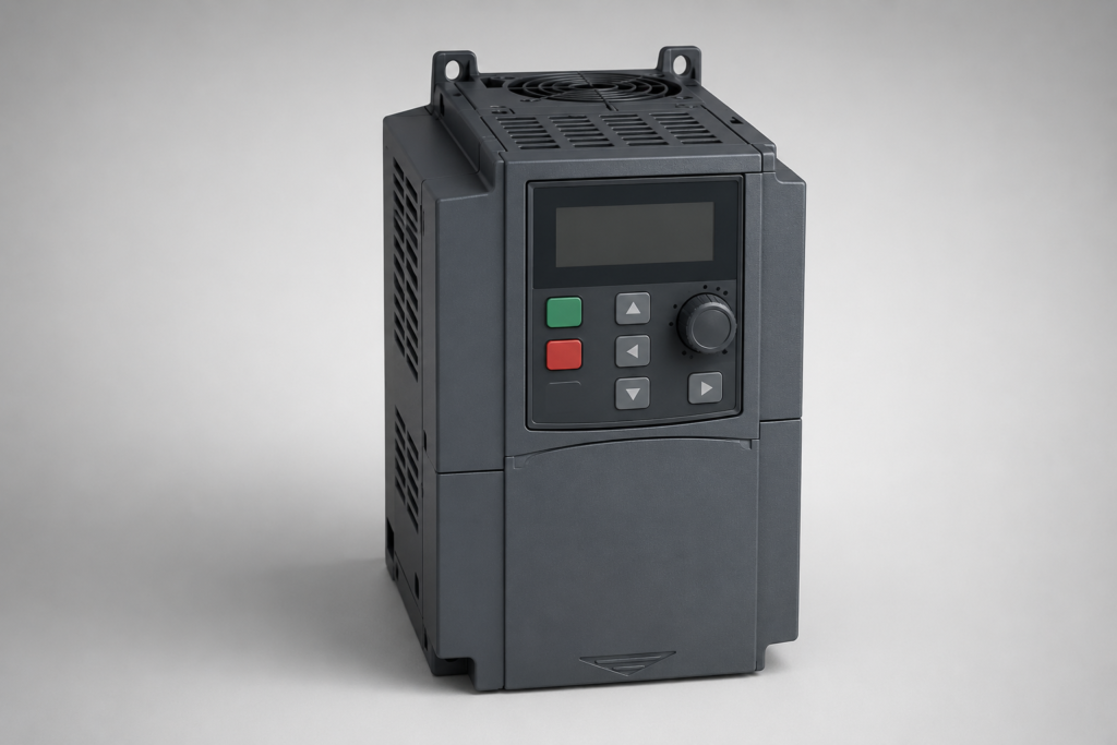
A VFD, or Variable Frequency Drive, is one of the most useful devices in modern industrial automation. It allows an electrical motor to run at controlled speeds instead of operating only at its rated speed. Because motor speed can be adjusted according to the process requirement, a VFD can improve production control, reduce mechanical stress, and help save electrical energy in many applications.
Today, VFD technology is widely used with induction motors, pumps, fans, conveyors, compressors, mixers, blowers, and many other industrial machines. Moreover, modern drives provide more than simple speed control. They can monitor motor conditions, provide protection functions, communicate with PLCs and HMIs, and support advanced control methods.
What Is a VFD and Why Is It Used?
A VFD is an electronic motor controller that regulates the speed and torque of an AC motor by controlling the frequency and voltage supplied to the motor. In a traditional motor installation, an AC induction motor connected directly to the mains normally operates close to its rated speed. However, many industrial processes do not need the motor to run at full speed all the time.
For example, a water pump may need to operate slowly when demand is low and faster when demand increases. A conveyor may require different speeds during different production stages. Similarly, a ventilation fan can often run below full speed when airflow requirements are reduced.
Instead of repeatedly switching a motor on and off, a VFD can continuously adjust its operating speed. As a result, the process becomes smoother and easier to control.
The drive also provides a controlled method for starting and stopping the motor. During acceleration, the frequency and voltage can be increased gradually. Therefore, the motor does not experience the same sudden electrical and mechanical conditions associated with a direct-on-line start.
How Does a VFD Work in an Industrial System?
Understanding how a VFD works becomes easier when its internal power path is divided into major stages. Although drive designs vary between manufacturers and models, the basic concept remains similar.
An AC supply first enters the drive. The incoming AC is then converted into DC by a rectifier section. After that, the DC passes through a DC link, where capacitors and related components help smooth and stabilize the electrical energy.
The final stage uses an inverter to convert the DC back into AC. Semiconductor switching devices rapidly turn the output on and off in a controlled pattern. By changing the switching pattern, the drive can produce an output with the required frequency and voltage characteristics.
The motor receives this controlled output and changes its operating speed accordingly.
The control system inside the drive continuously calculates how the power devices should switch. Depending on the drive design, this process may use methods such as Volts-per-Hertz control, sensorless vector control, or closed-loop vector control.
In practical terms, the VFD acts as an electronic bridge between the power source and the motor. Instead of allowing the motor to receive a fixed-frequency supply all the time, it creates an adjustable electrical output.
VFD Rectifier Section Explained
The rectifier is the first major power-conversion section in a typical VFD. Its main purpose is to convert incoming AC voltage into DC voltage.
For a three-phase drive, the rectifier commonly uses semiconductor devices arranged to convert the three-phase AC waveform into pulsating DC. In smaller or different drive configurations, other rectifier arrangements can be used.
The rectified output is not perfectly smooth. Therefore, the electrical energy moves into the DC-link section for additional filtering and stabilization.
This conversion stage is important because the inverter needs a DC source that it can switch rapidly and precisely. By first converting AC to DC, the drive gains greater control over the final motor output.
VFD DC Link and Its Importance
The DC link is the intermediate section between the rectifier and inverter. It commonly contains capacitors, and depending on the drive design, it may also include inductors or other filtering components.
A major function of the DC link is to reduce fluctuations in the rectified voltage. The stored electrical energy also helps support the inverter during rapid switching operations.
Because this section handles significant electrical energy, it can remain energized even after the incoming power has been disconnected. For that reason, proper safety procedures must be followed before opening a drive enclosure.
Technicians should never assume that a powered-down VFD is immediately safe to touch. The manufacturer's discharge time and maintenance instructions should always be observed.
VFD Inverter Section Explained
The inverter is the stage that creates the controlled AC output for the motor. It generally uses power semiconductor devices, such as insulated-gate bipolar transistors in many traditional industrial drives, although newer technologies and topologies are also available.
These switching devices operate at high speed. The controller determines when each device should conduct, creating a sequence of electrical pulses that produces the desired motor waveform.
The output frequency can be changed over a wide range depending on the drive and motor application. The voltage can also be adjusted to maintain suitable motor operation.
Although the motor does not receive a simple sine wave identical to the utility supply, modern motors and drives are designed to work together with these controlled waveforms. Output filters may also be used where an application requires additional waveform management.
VFD and Motor Frequency Relationship
Frequency has a direct relationship with the speed of an AC induction motor. For a simplified explanation, synchronous speed can be calculated using the motor's frequency and number of poles:
Synchronous Speed = (120 × Frequency) / Number of Poles
For example, a four-pole motor connected to a 50 Hz supply has a synchronous speed of approximately 1,500 RPM. The actual shaft speed will normally be slightly lower because induction motors operate with slip.
When the VFD reduces the frequency, motor speed also decreases. When the frequency increases within the motor's operating range, speed increases.
This relationship is one of the fundamental principles behind adjustable-speed motor control.
However, frequency should not be considered in isolation. Voltage must also be controlled appropriately so that the motor receives suitable magnetic flux. This is why many basic drives use a relationship between output voltage and output frequency.
VFD Volts-per-Hertz Control
Volts-per-Hertz, commonly called V/f control, is one of the traditional methods used by a VFD. The basic idea is to maintain an appropriate voltage-to-frequency relationship as the motor speed changes.
Suppose a motor is rated for 400 V at 50 Hz. When operating below its base frequency, the drive can reduce the output voltage together with the frequency. This helps maintain an appropriate magnetic flux level in the motor.
For many simple applications, V/f control provides reliable performance without requiring advanced motor feedback.
It is commonly suitable for applications such as fans, pumps, conveyors, and machines where very precise torque control is not the primary requirement.
Nevertheless, the correct motor parameters still need to be entered into the drive. Incorrect voltage, current, frequency, or motor data can lead to poor operation, excessive current, or drive faults.
VFD Vector Control
More demanding applications may require vector-based control. In vector control, the VFD uses a more detailed mathematical model of the motor to manage torque-producing and magnetizing components of current.
This allows the drive to respond more effectively to changing load conditions. Depending on the drive configuration, vector control can provide better low-speed torque, improved speed regulation, and faster response.
Sensorless vector control estimates motor behavior without requiring a physical encoder in many applications. Closed-loop vector control, on the other hand, may use an encoder or other feedback device to provide actual speed information.
These methods are useful for applications where the motor must maintain controlled speed or torque despite changing mechanical loads.
VFD Types Based on Input Supply
VFD systems can be classified according to their input and output configuration. One common category is the single-phase input drive, which is often found in smaller installations.
Another category is the three-phase input drive, which is widely used in industrial environments because three-phase motors are common in manufacturing and process equipment.
The required drive type depends on the available electrical supply, motor rating, installation requirements, and manufacturer specifications.
It is also important to understand that input phase configuration does not automatically determine every aspect of the motor output. Some drives can accept particular input configurations while producing a three-phase output within their rated limits. However, compatibility and derating requirements must always be checked in the manufacturer's documentation.
VFD Types Based on Motor Control Method
Another useful way to classify a VFD is by its control method.
Basic scalar drives normally use V/f control and are designed for straightforward speed regulation. They are often economical and relatively simple to configure.
Sensorless vector drives offer more advanced control and can provide improved performance under variable loading conditions. These drives are common in conveyors, machine tools, compressors, and other industrial applications.
Closed-loop vector drives can use encoder feedback for highly controlled speed and torque operation. They are appropriate for applications that demand accurate motion or strong low-speed performance.
The best option depends on the process rather than simply selecting the most advanced drive available.
VFD Applications in Industrial Automation
A VFD can be found in a wide range of industrial systems. Its versatility comes from the ability to control motor speed, acceleration, deceleration, and sometimes torque according to the application's requirements.
In pumping systems, the drive can adjust motor speed as flow or pressure requirements change. In HVAC systems, drives are frequently used with fans and pumps where variable operating speeds can improve process control.
Conveyor systems use drives to regulate belt speed according to production requirements. Mixing machines may need different speeds during filling, blending, and discharge operations.
Compressors, blowers, crushers, winding machines, and machine tools can also use adjustable-speed drives, although the control strategy and motor requirements differ from one application to another.
The important point is that the VFD should be selected according to the actual process, motor characteristics, load profile, and required control performance.
VFD Applications for Conveyor Systems
Conveyors are one of the clearest examples of where controlled motor speed provides practical value.
A direct-on-line motor starts at nearly full supply conditions, which can produce a sudden mechanical response. With a VFD, the conveyor motor can accelerate gradually according to programmed ramp settings.
Once running, the operator or PLC can change the speed when production requirements change. For example, a packaging line may slow the conveyor during inspection and increase the speed during normal production.
The drive can also support controlled deceleration. This is especially useful when a conveyor carries heavy products because an abrupt stop can create mechanical shock or product instability.
When multiple conveyor motors are coordinated through PLC logic and drive communication, the overall production line can become more flexible and easier to automate.
VFD Applications for Water Pumps
Pump systems often benefit significantly from variable-speed operation because water demand is not always constant.
A fixed-speed pump may produce more flow than necessary during low-demand periods. Flow can then be restricted mechanically through valves, but the motor may still consume substantial energy.
With a VFD, motor speed can be adjusted to match the required flow or pressure. A pressure sensor can provide feedback to a controller, which then adjusts drive speed according to the process demand.
This arrangement can reduce unnecessary throttling and improve system control.
However, energy savings should not be assumed simply because a drive is installed. Actual savings depend on the pump type, system curve, operating conditions, control strategy, and amount of time spent at reduced speed.
VFD Applications for Fans and Blowers
Fans and blowers are another common application. Industrial ventilation, air handling, dust collection, and cooling systems may require different airflow levels throughout the day.
A VFD allows the fan motor speed to be adjusted according to airflow or pressure requirements. Because fan systems can have strongly speed-dependent power characteristics, reducing speed can sometimes produce substantial energy savings compared with running continuously at full speed.
For example, a factory ventilation system may operate at a lower speed during periods of reduced production and increase speed when temperature or airflow requirements rise.
Pressure sensors, temperature sensors, and PLC systems can be integrated with the drive to create automatic control.
VFD Applications for Compressors
Compressors require careful control because their load characteristics can vary widely.
A VFD can be used with suitable compressor designs to regulate motor speed according to demand. This can help avoid excessive cycling and provide smoother operation.
However, not every compressor can be controlled in the same manner. Screw compressors, centrifugal compressors, reciprocating compressors, and other designs have different operating requirements.
Therefore, compatibility between the drive, motor, compressor, lubrication system, and control strategy must be evaluated before installation.
VFD Applications in Industrial PLC Systems
A VFD becomes even more powerful when it is integrated with a PLC. The PLC can send commands such as start, stop, speed reference, direction, and operating mode.
Depending on the installation, communication may take place through digital inputs and outputs, analog signals, or industrial communication networks.
For example, a PLC might read a pressure sensor and calculate the required motor speed. It can then send a speed reference to the drive. The drive controls the motor while reporting information such as actual frequency, current, alarms, and fault status back to the PLC.
This creates a coordinated control system instead of treating the motor drive as a standalone device.
VFD Communication with HMI and SCADA
Modern industrial systems commonly connect the VFD to HMIs or SCADA systems. Operators can then view drive parameters, motor speed, current, alarms, and operating status from a central interface.
For example, an HMI screen may allow an operator to enter a speed reference while displaying the actual running frequency. A SCADA system can record operating data and show historical trends.
Industrial networks can make this communication more efficient because one communication link may carry multiple parameters without requiring separate hardwired signals for every value.
The actual protocol depends on the equipment. Common industrial communication technologies include Modbus, PROFINET, EtherNet/IP, CAN-based networks, and other manufacturer-specific or standardized systems.
VFD Acceleration and Deceleration Control
One of the practical advantages of a VFD is its ability to control acceleration and deceleration.
Acceleration time determines how quickly the drive increases motor speed. A longer ramp can reduce mechanical shock and limit the sudden demand associated with starting a heavy load.
Deceleration time controls how quickly the motor slows down. However, reducing speed converts mechanical energy back toward the electrical system, and that energy must be handled by the drive.
If deceleration is too aggressive, the DC-link voltage can rise and cause an overvoltage fault. In suitable applications, a braking resistor or regenerative braking system may be used to manage this energy.
Therefore, ramp settings should always be selected according to the motor, load inertia, stopping requirements, and drive capabilities.
VFD Forward and Reverse Operation
Many applications require a motor to rotate in both directions. A VFD can often provide forward and reverse control through programmed commands.
For example, a conveyor may need reverse movement during maintenance, while a material-handling machine may require directional changes during its normal cycle.
Direction can typically be controlled through digital inputs, keypad commands, PLC communication, or another supported interface.
However, reversing a motor under heavy load requires careful consideration. The drive may need to decelerate the motor before changing direction, depending on the application and configuration.
VFD Motor Protection Functions
Modern drives often include several protective functions. These may monitor conditions such as overcurrent, overvoltage, undervoltage, overload, overheating, and other abnormal operating states.
A VFD may also monitor motor current and use programmed motor data to provide electronic overload protection.
These protections are valuable because they can detect abnormal conditions and shut down the system before equipment damage becomes more severe.
Still, drive protection should not be considered a replacement for correct electrical protection, grounding, wiring, disconnects, fuses, circuit breakers, and properly designed safety systems.
VFD and Motor Overheating
Motor heating can become a concern at low speeds, especially when a standard motor relies on a shaft-mounted cooling fan.
When the motor operates much slower than its rated speed, the cooling fan may also rotate more slowly. As a result, the motor may not dissipate heat as effectively.
A VFD installation must therefore consider the motor's thermal characteristics, load torque, operating speed, and cooling method.
In demanding applications, an independently powered cooling fan or inverter-duty motor may be more appropriate.
The drive's current limits and thermal protection should also be configured according to the motor manufacturer's specifications.
Why VFD Selection Matters
Choosing a VFD should never be based only on motor horsepower. Several electrical and mechanical factors must be considered.
The motor's voltage, full-load current, frequency, phase configuration, operating speed, load type, overload requirement, and duty cycle all affect drive selection.
The application's environment also matters. Dust, moisture, ambient temperature, altitude, enclosure design, and installation location can influence the required drive rating.
For example, a conveyor lifting a heavy load may require different overload capability from a fan operating with a relatively predictable load.
Therefore, the current rating and overload characteristics of the drive should be checked carefully rather than selecting a model solely because its advertised horsepower appears to match the motor.
VFD Best Practices for Industrial Installations
A successful installation starts with correct electrical design. Wiring should follow the drive manufacturer's instructions, and the motor cable, grounding arrangement, protection devices, and enclosure should be selected appropriately.
The motor nameplate data should be entered correctly into the drive. Parameters such as rated voltage, rated current, frequency, and motor speed may be required depending on the control method.
Cable routing is also important because fast switching can generate electromagnetic interference. Separating power cables from sensitive signal wiring and following recommended grounding and shielding practices can help reduce communication and control problems.
Finally, commissioning should be performed carefully. The motor should first be tested under controlled conditions before the entire machine is placed into normal production.
Frequently Asked Questions About VFD
What is a VFD?
A VFD, or Variable Frequency Drive, controls the speed and torque of an AC motor by adjusting the frequency and voltage supplied to the motor. Industries use this technology to achieve smoother motor operation and better process control.
How does a VFD control motor speed?
A VFD first converts incoming AC power into DC power and then converts that DC power back into controlled AC output. By changing the output frequency, the drive changes the motor's operating speed. It also adjusts voltage to maintain suitable motor performance.
Can a VFD save energy?
Yes, a VFD can reduce energy consumption in suitable applications, especially with pumps and fans. When the process does not require full motor speed, the drive can lower the motor speed instead of keeping it at maximum speed. Actual savings depend on the load, operating conditions, and control method.
Can a VFD control a three-phase motor?
Yes, many industrial VFDs control three-phase induction motors. Before installation, you should check the motor voltage, current, frequency, phase configuration, and the drive's rated capacity to ensure proper compatibility.
Can a VFD work with a PLC?
Yes, a VFD can communicate with a PLC through digital signals, analog signals, or industrial communication networks. The PLC can control start and stop commands, speed references, direction, and other functions while the drive sends status and fault information back to the PLC.
Why does a VFD trip on overcurrent?
A VFD may trip on overcurrent when the motor experiences excessive load, incorrect acceleration settings, mechanical problems, wiring issues, or an unsuitable motor-drive configuration. Checking motor current, load conditions, acceleration time, and drive parameters can help identify the cause.
What is the difference between V/f control and vector control?
V/f control maintains a suitable relationship between motor voltage and frequency and works well for many basic applications. Vector control uses a more advanced control method to provide better speed regulation and torque performance, particularly when the application requires stronger control at low speeds.
How do I choose the correct VFD?
Start with the motor's rated voltage, full-load current, frequency, phase configuration, and required operating speed. Then consider the application's load type, overload demand, acceleration and deceleration requirements, environment, communication needs, and braking requirements. Selecting the drive from the motor's current and application requirements usually provides a more reliable result than choosing only by horsepower.
Conclusion
A VFD provides a practical way to control AC motors according to actual process requirements. Instead of forcing a motor to operate at one fixed speed, it allows the control system to adjust speed, acceleration, deceleration, and operating conditions more effectively.
Its internal rectifier, DC link, and inverter work together to create controlled AC power for the motor. At the same time, modern drives can provide protection, monitoring, communication, and integration with PLC, HMI, and SCADA systems.
The right drive can improve process control and, in suitable applications, reduce energy consumption and mechanical stress. However, good results depend on correct sizing, motor compatibility, parameter configuration, wiring, cooling, grounding, and commissioning.
For industrial automation, understanding how a VFD works helps engineers and technicians build safer, more efficient, and more reliable motor-control systems. As automation continues to develop, variable-speed drives will remain an important part of modern industrial equipment.

Pingback: VFD Harmonics: Causes, Effects & Mitigation Guide
Pingback: VFD Overvoltage Fault: Causes, Diagnosis & Solutions