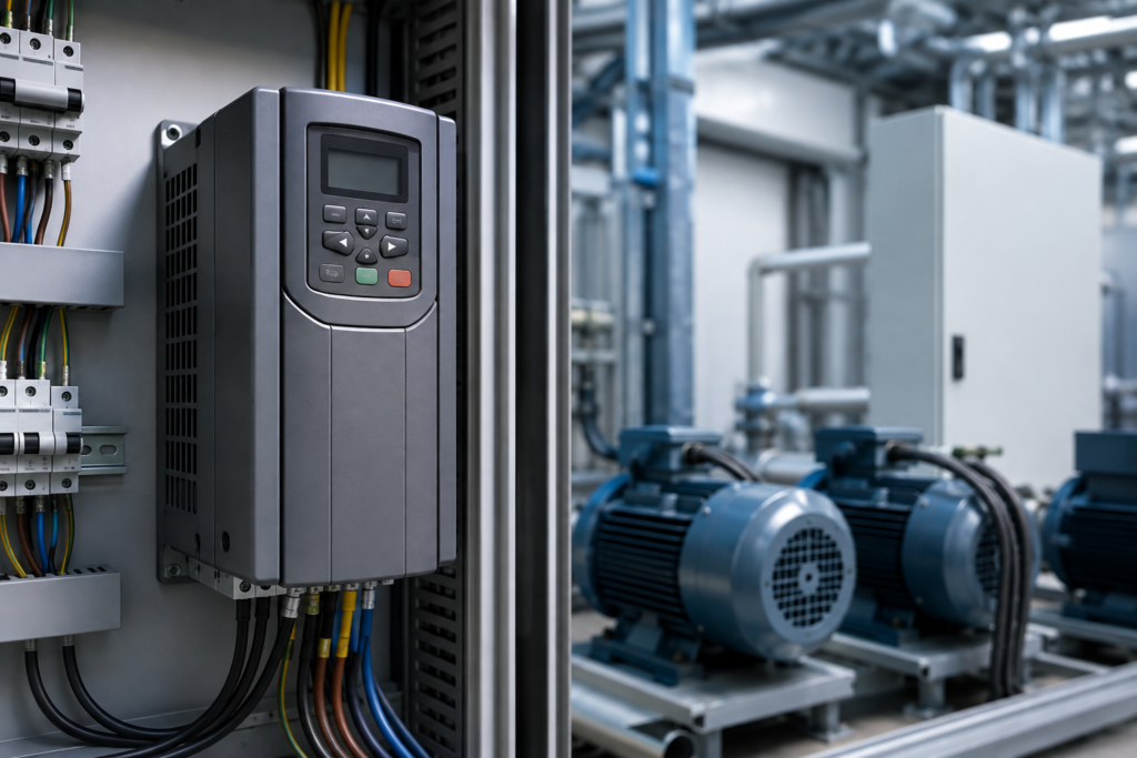
VFD Harmonics are an important power quality concern in modern industrial electrical systems. Variable Frequency Drives (VFDs) are widely used to control the speed and torque of AC motors, improve process control, and reduce energy consumption. However, the electronic conversion process inside a VFD can produce distorted input current. When several drives operate together, this distortion can become a significant concern for the electrical network.
In a properly designed power system, voltage and current waveforms should remain close to a smooth sinusoidal shape. A VFD, however, does not always draw current in the same smooth pattern as a conventional linear load. Instead, its input rectifier draws current in pulses. These current pulses introduce additional frequency components into the electrical system, commonly known as harmonics.
Understanding VFD Harmonics is therefore important for anyone involved in industrial electrical design, maintenance, commissioning, or automation. Although harmonic distortion may not always cause an immediate failure, excessive levels can increase equipment heating, electrical losses, and operating problems over time.
What Are VFD Harmonics?
VFD Harmonics are electrical currents or voltages that occur at frequencies that are integer multiples of the fundamental power frequency. In many industrial systems, the fundamental frequency is either 50 Hz or 60 Hz. Harmonics appear above this fundamental frequency and can distort the original waveform.
For example, in a 50 Hz power system, the 3rd harmonic has a frequency of 150 Hz, while the 5th harmonic occurs at 250 Hz. The 7th harmonic occurs at 350 Hz. These components combine with the fundamental waveform and change its shape.
The presence of harmonics does not necessarily mean that a system is unsafe. The real concern is the magnitude of harmonic distortion and how it interacts with the rest of the electrical installation. Therefore, engineers normally evaluate harmonic levels at important points in the distribution system rather than judging a VFD by itself.
How Do VFD Harmonics Develop?
To understand how VFD Harmonics develop, it helps to look at the basic power-conversion process inside a VFD.
A typical VFD first receives AC power from the electrical supply. Its rectifier section converts that AC power into DC power. The DC-link section then stores and smooths the energy before the inverter section converts it back into a controlled AC output for the motor.
The problem begins at the input stage. A conventional diode bridge rectifier does not draw current continuously throughout the entire AC cycle. Instead, it draws current when the input voltage is high enough to charge the DC-link capacitor. As a result, the input current becomes non-sinusoidal.
This non-sinusoidal current is the main reason VFD Harmonics appear on the supply side of the drive. The motor may receive a controlled output waveform, but the upstream electrical network still has to supply the distorted input current required by the converter.
Why Are VFD Harmonics Important in Industrial Plants?
VFD Harmonics become more important as the number and size of drives increase. A small drive operating on a strong electrical network may have very little noticeable effect. However, a large industrial facility with dozens or hundreds of VFDs can create a much greater cumulative impact.
Harmonic currents can flow through transformers, cables, switchgear, and other parts of the distribution system. Consequently, these components may experience additional losses and heating. In systems with limited electrical capacity, the impact can become more noticeable.
Furthermore, harmonic distortion can interact with power factor correction equipment. Under certain conditions, capacitors and system inductance can create resonance, which may increase specific harmonic currents. For this reason, harmonic performance should be considered when designing or expanding an industrial electrical system.
Common Sources of VFD Harmonics
The most common source of VFD Harmonics is the input rectifier used in conventional AC drives. Six-pulse rectifiers are widely used because they are relatively simple, reliable, and economical. However, their current waveform contains significant harmonic components.
VFDs are not the only nonlinear loads in a modern industrial facility. UPS systems, battery chargers, switching power supplies, welding machines, and other electronic converters can also introduce harmonics.
Therefore, a plant may experience harmonic distortion from several sources at the same time. A proper analysis should consider the entire electrical network rather than assuming that one VFD is responsible for all observed distortion.
Which Harmonics Are Common in VFD Systems?
In conventional six-pulse VFDs, certain harmonic orders are especially common. The 5th and 7th harmonics are typically among the more significant low-order components, followed by higher orders such as the 11th and 13th.
For example, a 50 Hz system produces a 5th harmonic at 250 Hz and a 7th harmonic at 350 Hz. These additional frequency components contribute to the overall distortion of the current waveform.
However, the exact harmonic spectrum depends on the drive design, operating conditions, supply impedance, and other connected loads. Therefore, engineers should rely on actual measurements or manufacturer data when determining the harmonic profile of a specific installation.
Effects of VFD Harmonics on Electrical Equipment
Excessive VFD Harmonics can increase losses in transformers and conductors. Because harmonic currents contribute to the total RMS current, equipment can operate at higher temperatures than expected. Over time, this additional heating may reduce efficiency and contribute to premature component aging.
Transformers can also experience increased winding and core losses when exposed to distorted current and voltage. Similarly, cables and busbars may experience additional heating depending on the harmonic content and installation conditions.
In addition, sensitive electronic equipment can sometimes be affected by poor power quality. Communication systems, measurement devices, controllers, and other electronic equipment may become more vulnerable when significant electrical distortion is present.
For this reason, VFD Harmonics should be treated as a system-level power quality issue rather than simply a characteristic of the drive itself.
VFD Harmonics and Total Harmonic Distortion
Total Harmonic Distortion, commonly called THD, is one of the main ways engineers describe harmonic distortion. THD compares the combined magnitude of harmonic components with the fundamental component.
A higher THD value indicates that the waveform contains more distortion relative to its fundamental component. However, the acceptable level depends on the electrical system, equipment, applicable standards, and location where the measurement is taken.
When evaluating VFD Harmonics, engineers may examine both current THD and voltage THD. Current distortion is particularly relevant for nonlinear loads such as VFDs, while voltage distortion reflects how those harmonic currents interact with the impedance of the electrical network.
Main Causes of VFD Harmonics
The main cause of VFD Harmonics is the way a conventional drive converts incoming AC power into DC power. The input rectifier draws current in short pulses instead of following the smooth shape of the supply voltage. Consequently, the current waveform contains multiple harmonic components.
The type of rectifier also matters. A traditional six-pulse VFD is a common source of low-order harmonic currents. In contrast, drives with technologies such as active front ends can significantly change the input current waveform and reduce harmonic distortion.
System conditions also influence VFD Harmonics. A weak electrical supply, high source impedance, large drive capacity, or several nonlinear loads operating together can make harmonic distortion more noticeable. Therefore, engineers should consider both the VFD and the electrical network when investigating a harmonic problem.
VFD Harmonics and Transformer Heating
VFD Harmonics can increase the electrical stress placed on transformers. Harmonic currents create additional losses in transformer windings and magnetic components. As these losses increase, the transformer can operate at a higher temperature than it would under a clean sinusoidal load.
This additional heating may reduce efficiency and, over time, affect transformer insulation life. In facilities with many large drives, the effect can become particularly important because the transformer continuously supplies distorted current.
For this reason, transformer selection should consider the expected nonlinear load rather than relying only on the total connected kVA. Proper loading and harmonic assessment can help prevent unnecessary thermal stress.
VFD Harmonics and Motor Performance
Although a VFD controls the motor output, VFD Harmonics on the supply side can still influence overall motor-system performance indirectly. Harmonic distortion can contribute to additional losses in motors and other magnetic equipment connected to the same electrical network.
Higher-frequency components may increase electromagnetic losses and create additional heating. As a result, motors operating in a heavily distorted electrical environment may require closer monitoring of temperature and operating conditions.
However, it is important to distinguish input-side harmonics from the PWM waveform produced by the VFD output stage. These are related to different parts of the drive system and should not be treated as exactly the same problem.
VFD Harmonics and Power Factor
VFD Harmonics can also affect how engineers evaluate power factor. A VFD may have a reasonable displacement power factor while still drawing a highly distorted current waveform. Therefore, simply looking at one power-factor value may not provide a complete picture of the electrical conditions.
True power factor reflects both displacement and distortion effects. As harmonic current increases, the overall power factor can decrease even when the phase relationship between voltage and current remains relatively good.
Consequently, facilities with many VFDs should evaluate harmonic distortion together with power factor instead of assuming that improving one automatically solves the other.
Measuring VFD Harmonics in an Industrial System
Accurate measurement is an important step when diagnosing VFD Harmonics. Engineers commonly use a power quality analyzer or suitable electrical measurement equipment to examine voltage, current, harmonic components, and THD.
Measurements should be taken at appropriate locations within the electrical distribution system. For example, checking the VFD input, distribution panel, transformer secondary, or point of common coupling can reveal how harmonic currents move through the facility.
It is also useful to record data under different operating conditions. A drive operating at low load may produce a different harmonic profile than the same drive operating near full capacity. Therefore, measurements taken at only one moment may not represent the actual worst-case condition.
Understanding THD When Analyzing VFD Harmonics
Total Harmonic Distortion, or THD, provides a useful way to quantify VFD Harmonics. Current THD indicates how much harmonic current exists relative to the fundamental current, while voltage THD indicates distortion in the supply voltage.
A high current THD does not automatically mean that voltage distortion will be equally high. The relationship depends heavily on the impedance and strength of the electrical system. A strong supply may absorb substantial harmonic current with relatively little voltage distortion, while a weaker system can experience a much greater voltage response.
Therefore, THD should always be interpreted in context. Engineers should consider the measurement location, system conditions, connected loads, and applicable power-quality requirements before deciding whether corrective action is necessary.
Passive Methods for Reducing VFD Harmonics
One practical approach to controlling VFD Harmonics is to improve the input characteristics of the drive. Line reactors and DC-link chokes are commonly used for this purpose. These components add impedance to the circuit and can help smooth the current drawn by the VFD.
Passive harmonic filters provide another option. They use combinations of inductors, capacitors, and other components to reduce selected harmonic currents. When correctly designed, a passive filter can provide a cost-effective solution for a predictable harmonic environment.
However, passive equipment must be selected carefully. Poorly designed filtering can interact with system impedance and create unwanted resonance. Therefore, a harmonic study should normally support the final filter selection.
Active Harmonic Filters for VFD Harmonics
Active harmonic filters provide a more flexible approach to VFD Harmonics. Instead of relying only on passive components, an active filter measures harmonic current and generates a compensating current that reduces the unwanted components.
This technology can be especially useful in facilities where the load changes frequently. Since industrial plants often add or remove equipment over time, the harmonic profile may not remain constant. An active filter can respond dynamically to changing conditions.
Even so, active filters are not automatically the best choice for every installation. Cost, available space, system capacity, harmonic severity, and future expansion plans should all be considered before selecting a solution.
Choosing the Right VFD Harmonics Mitigation Method
The most effective way to manage VFD Harmonics is to select a mitigation method based on actual system requirements rather than applying the same solution everywhere.
For a small installation, a line reactor or DC choke may provide sufficient improvement. For larger systems with several drives, passive filters, multi-pulse solutions, or active front-end drives may be more appropriate. In facilities with rapidly changing loads, an active harmonic filter can offer additional flexibility.
Most importantly, engineers should evaluate the electrical network before installing mitigation equipment. Understanding the existing harmonic spectrum, transformer capacity, system impedance, and future load growth can prevent unnecessary expense and improve long-term reliability.
Best Practices for Managing VFD Harmonics
Good harmonic management starts during the design stage. Selecting suitable VFD technology, sizing transformers correctly, and considering the total nonlinear load can reduce problems before the plant becomes operational.
Regular monitoring is equally important. As production equipment changes, the harmonic environment can change as well. New drives, UPS systems, or other electronic loads may increase distortion even when the original installation performed normally.
Therefore, VFD Harmonics should be considered an ongoing power-quality issue. Periodic measurements, preventive maintenance, and timely corrective action can help industrial facilities maintain stable electrical performance.
12-Pulse and 18-Pulse Drives for VFD Harmonics
One way to reduce VFD Harmonics at the design stage is to use a rectifier with more than six pulses. Twelve-pulse and 18-pulse drives use phase-shifting transformer arrangements and multiple rectifier bridges to reduce the magnitude of several lower-order harmonic components.
Compared with a conventional six-pulse drive, a 12-pulse configuration can significantly reduce certain characteristic harmonics on the input side. An 18-pulse arrangement can provide further improvement, although it generally requires additional equipment and more complex installation.
Because of this, multi-pulse technology can be attractive in large industrial applications where harmonic performance is an important design requirement. However, the additional transformer requirements, physical space, cost, and maintenance should be considered before selecting this approach.
Active Front End Drives and VFD Harmonics
An Active Front End (AFE) is another technology used to control VFD Harmonics. Unlike a traditional diode rectifier, an AFE uses controlled power semiconductor devices to regulate the input current waveform.
As a result, an AFE can draw current much closer to a sinusoidal shape and can provide a high input power factor. It can also allow energy to flow back toward the supply during regenerative operation, which makes the technology useful for applications such as elevators, test benches, cranes, and high-inertia machinery.
Nevertheless, AFE drives are generally more sophisticated and can cost more than conventional VFDs. Therefore, they are most beneficial when low harmonic distortion, regenerative capability, or advanced energy management justifies the additional investment.
Line Reactors and DC Chokes for VFD Harmonics
Line reactors and DC chokes are relatively simple components that can help manage VFD Harmonics in many installations. A line reactor is installed on the AC input side, while a DC choke is installed within the DC-link circuit of the drive.
These components add impedance to the circuit and limit abrupt changes in current. Consequently, they can reduce peak input current and improve the overall current waveform.
They are not a complete solution for every harmonic problem, however. Their effectiveness depends on the drive design and electrical system. Therefore, engineers should check manufacturer recommendations and actual system measurements before relying on these components as the primary mitigation method.
Harmonic Filters for VFD Harmonics
Harmonic filters are specifically designed to reduce unwanted frequency components from an electrical system. VFD Harmonics can be addressed with either passive or active filtering, depending on the application and required performance.
Passive filters target specific harmonic frequencies using electrical components such as inductors and capacitors. They can be economical and effective when the harmonic spectrum remains relatively predictable. However, their design must account for system impedance and possible resonance.
Active harmonic filters work differently. They continuously monitor the electrical waveform and inject compensating currents to reduce harmonic components. Because they can respond to changing load conditions, active filters are often useful in facilities where the number and operating conditions of VFDs change frequently.
How to Troubleshoot VFD Harmonics Problems
When investigating VFD Harmonics, troubleshooting should begin with measurement rather than assumptions. A power quality analyzer can provide valuable information about voltage distortion, current distortion, individual harmonic orders, THD, and system loading.
First, engineers should identify where the distortion is highest. Measurements at the VFD input, distribution panel, transformer, and point of common coupling can help determine how harmonic currents move through the system.
Next, operating conditions should be compared. A plant may show acceptable harmonic performance during light production but experience higher distortion when multiple large drives operate simultaneously. Therefore, measurements should ideally cover representative operating conditions instead of relying on a single snapshot.
Signs of Excessive VFD Harmonics
Certain operating symptoms can indicate that VFD Harmonics deserve further investigation. Unusual transformer heating, overloaded conductors, unexplained capacitor failures, excessive electrical losses, and unexpected behavior from sensitive equipment can all justify a power-quality assessment.
However, these symptoms do not automatically prove that harmonics are the cause. Similar problems can result from poor connections, incorrect sizing, voltage imbalance, overloads, or other electrical faults.
For that reason, engineers should confirm the actual condition with appropriate measurements. Once the harmonic spectrum is known, the corrective action can be selected with much greater confidence.
Designing an Industrial System to Control VFD Harmonics
Good system design can prevent many VFD Harmonics problems before they occur. The first step is to estimate the total nonlinear load and understand how many drives will operate at the same time.
The electrical distribution system should then be evaluated for transformer capacity, short-circuit strength, conductor sizing, and expected voltage distortion. Drive selection should also consider the required harmonic performance instead of focusing only on motor power and speed control.
In large projects, a harmonic study can be especially valuable. It can identify potential problem areas before equipment is installed and can help engineers compare different mitigation technologies objectively.
VFD Harmonics and Future Plant Expansion
A harmonic solution that works well today may not remain sufficient after a facility expands. VFD Harmonics can increase when additional drives, UPS units, chargers, or other nonlinear equipment are added to the electrical network.
Therefore, future load growth should be considered when designing mitigation equipment. Leaving adequate capacity for additional filtering or selecting equipment that can accommodate changing loads can prevent expensive modifications later.
This approach is especially important in manufacturing facilities where production lines are frequently upgraded. Planning for expansion can make the electrical system more flexible and reduce unexpected power-quality problems.
Practical Steps to Reduce VFD Harmonics
The most effective approach begins with accurate measurement and a clear understanding of the electrical system. Once the harmonic sources have been identified, engineers can select an appropriate combination of drive technology and mitigation equipment.
For smaller applications, line reactors or DC chokes may provide a practical improvement. Larger installations may benefit from passive filters, active harmonic filters, multi-pulse drives, or active front-end technology. The correct choice depends on the required harmonic performance, load characteristics, available space, project budget, and future expansion.
Most importantly, mitigation equipment should be designed as part of the complete electrical system. Installing a filter without understanding the network can create new problems, including resonance or unexpected interactions with other equipment.
VFD Harmonics: Maintenance and Monitoring Best Practices
Managing VFD Harmonics does not end after commissioning. Industrial electrical systems change over time, and these changes can affect power quality. New drives may be installed, production loads may increase, or capacitor banks may be modified.
Regular power-quality monitoring can help identify changes before they become serious problems. Maintenance teams should also inspect connections, ventilation, drive components, filters, reactors, and other associated equipment according to the applicable maintenance plan.
In addition, recorded measurement data can be useful when diagnosing recurring problems. Comparing current readings with historical values can help engineers recognize trends and determine whether harmonic distortion is increasing.
Frequently Asked Questions About VFD Harmonics
What are VFD Harmonics?
VFD Harmonics are unwanted frequency components created when a variable frequency drive draws non-sinusoidal current from the electrical supply.
What causes VFD Harmonics?
They are mainly caused by the input rectifier of a VFD, which draws current in pulses instead of following a smooth sinusoidal waveform.
How do VFD Harmonics affect electrical equipment?
Excessive harmonics can cause additional heating and losses in transformers, cables, motors, and other electrical equipment. They can also contribute to power-quality problems.
How can VFD Harmonics be reduced?
Common solutions include line reactors, DC chokes, passive harmonic filters, active harmonic filters, multi-pulse drives, and active front-end technology.
What is THD in a VFD system?
THD, or Total Harmonic Distortion, measures the amount of harmonic distortion present in a waveform compared with its fundamental component. Lower THD generally indicates a cleaner waveform.
Conclusion
VFD Harmonics are an important consideration in modern industrial power systems. While variable frequency drives provide precise motor control and significant operational benefits, their power-conversion process can introduce harmonic distortion into the electrical network. When distortion becomes excessive, it can contribute to additional heating, losses, equipment stress, and power-quality problems.
Fortunately, these issues can be managed through proper engineering and monitoring. Line reactors, DC chokes, harmonic filters, multi-pulse drives, and active front-end technology can help reduce harmonic distortion when selected for the right application. In addition, regular power-quality measurements can reveal changing conditions before they become major problems.
Ultimately, successful harmonic management starts with understanding the complete electrical system. By selecting suitable VFD technology, evaluating harmonic levels, and applying an appropriate mitigation strategy, industrial facilities can improve power quality, protect equipment, and achieve more reliable long-term operation.