Introduction
S7-200 SMART Wiring is one of the most important parts of a successful PLC installation. A well-planned wiring layout helps the Siemens S7-200 SMART CPU ST60 operate safely, communicate accurately, and control industrial equipment without unexpected interruptions. Moreover, proper wiring reduces electrical noise, simplifies maintenance, and improves the overall reliability of an automation system.
Many beginners focus only on PLC programming. However, correct wiring is equally important because every sensor, switch, actuator, and communication device depends on secure electrical connections. As a result, even the best PLC program cannot perform correctly if the wiring contains mistakes.
The Siemens S7-200 SMART CPU ST60 is widely used in industrial automation because it offers reliable performance, flexible I/O options, and simple programming. Therefore, engineers use it in conveyor systems, water treatment plants, packaging machines, process control, and many other industrial applications.
This guide explains S7-200 SMART Wiring step by step using professional engineering practices. You will learn how to connect the power supply, digital inputs, digital outputs, analog signals, and communication interfaces while following safe wiring methods. In addition, you will discover practical tips that help improve system reliability and simplify future maintenance.
What Is S7-200 SMART Wiring?
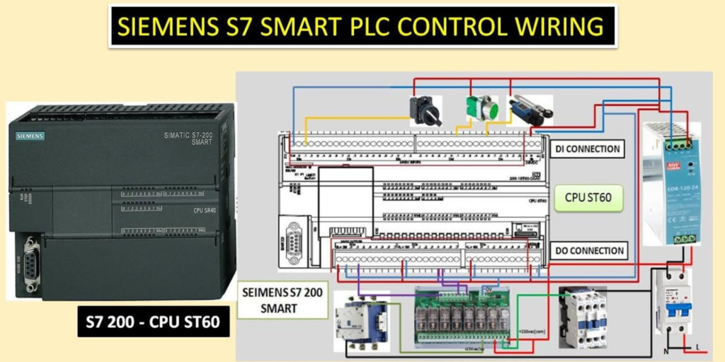
S7-200 SMART Wiring refers to the complete electrical connection process for the Siemens S7-200 SMART CPU ST60 PLC. It includes connecting the power supply, input devices, output devices, communication ports, grounding, and protection components. Every connection plays an important role in keeping the automation system stable and reliable.
Unlike simple electrical installations, PLC wiring requires careful planning. Engineers must organize every wire correctly to ensure accurate signal transmission and safe equipment operation. Consequently, a clean wiring layout reduces troubleshooting time and minimizes installation errors.
Furthermore, professional wiring improves long-term maintenance. Clearly labeled wires and organized terminal connections allow technicians to identify faults quickly without disconnecting unnecessary components. Therefore, structured wiring saves valuable maintenance time and increases overall productivity.
Modern industrial facilities also require reliable communication between PLCs, HMIs, variable frequency drives, and sensors. Proper wiring supports stable data exchange while protecting communication signals from electrical interference.
For these reasons, engineers always consider wiring quality as important as PLC programming itself.
Why Proper S7-200 SMART Wiring Matters
Reliable automation begins with reliable wiring. Every signal received by the PLC passes through electrical connections before reaching the controller. Therefore, poor wiring can create false signals, communication failures, and unexpected machine behavior.
A properly wired PLC system improves operational safety because all control devices communicate correctly with the controller. Emergency stop buttons, safety switches, and protective sensors respond immediately whenever dangerous conditions occur. As a result, operators and equipment remain better protected.
Moreover, organized wiring improves maintenance efficiency. Engineers can locate wires quickly because each terminal follows a logical arrangement. Consequently, troubleshooting becomes faster, and production resumes sooner after maintenance.
Correct wiring also protects electronic components from electrical damage. Stable voltage, proper grounding, and suitable protective devices help extend the life of the PLC and connected equipment. In addition, good wiring reduces electrical noise that may affect sensitive analog or communication signals.
Companies also benefit financially from professional wiring practices. Fewer wiring mistakes reduce installation time, minimize downtime, and lower long-term maintenance costs.
Understanding the Siemens S7-200 SMART CPU ST60
The Siemens S7-200 SMART CPU ST60 is a compact programmable logic controller designed for small and medium-sized automation projects. It combines digital inputs, digital outputs, communication capabilities, and flexible programming features within one controller.
Many industries choose this PLC because it delivers reliable performance while remaining easy to install and program. Engineers commonly use it in manufacturing, water treatment, food processing, material handling, packaging, textile production, and building automation.
The controller supports communication with HMIs, expansion modules, and other automation devices. Consequently, engineers can build complete control systems without adding unnecessary hardware.
Another advantage involves future expansion. Additional modules allow the automation system to grow whenever production requirements increase. Therefore, the PLC remains suitable for both current and future applications.
Although the controller provides advanced features, successful operation still depends on correct S7-200 SMART Wiring. Every connection should follow recommended engineering practices to ensure reliable performance.
S7-200 SMART Wiring for Power Supply
The power supply provides the foundation for every PLC installation. Without stable electrical power, the controller cannot process signals or control connected devices. Therefore, engineers should always begin the installation by verifying the correct power requirements.
Before connecting the PLC, confirm that the supply voltage matches the CPU specifications. Using an incorrect voltage may damage electronic components and interrupt machine operation. Consequently, checking the power source before installation helps prevent costly equipment failures.
Next, connect the power terminals according to the wiring diagram supplied with the controller. Tighten every terminal securely because loose connections may create voltage drops or intermittent faults during operation.
Furthermore, install proper circuit protection before energizing the PLC. Circuit breakers or suitable protective devices help protect the controller from electrical faults and overload conditions. This additional protection improves equipment safety and extends service life.
Engineers should also separate power cables from communication and signal cables whenever possible. This simple practice reduces electromagnetic interference and improves signal quality throughout the control system.
Finally, inspect every connection carefully before applying power. A complete visual inspection often identifies wiring mistakes before they affect equipment operation. As a result, commissioning becomes smoother and unexpected startup problems decrease.
Basic Wiring Preparation Before Installation
Proper preparation makes every PLC installation easier and safer. Before starting S7-200 SMART Wiring, gather all required components, verify the electrical drawings, and inspect every cable for physical damage.
Choose high-quality industrial cables that match the application. In addition, use correctly sized conductors to handle the expected electrical load without excessive voltage loss.
Wire labeling also plays an important role during installation. Every wire should carry a clear identification number or tag. Consequently, future maintenance becomes much faster because technicians can identify each connection immediately.
Moreover, route cables neatly inside the control panel. Keep communication cables away from high-voltage power lines to reduce electrical interference. Organized cable routing also improves airflow inside the panel and creates a more professional installation.
Before powering the PLC, perform a final inspection of every terminal, grounding point, and protective device. This careful approach reduces commissioning problems and increases overall system reliability.
S7-200 SMART Wiring for Digital Inputs
Digital inputs allow the PLC to receive signals from field devices. These devices include push buttons, limit switches, proximity sensors, photoelectric sensors, and emergency stop contacts. Every input sends a simple ON or OFF signal to the PLC.
Good S7-200 SMART Wiring starts with correct input connections. First, identify each input terminal before connecting any wire. Next, match every sensor with the correct PLC input. This simple step prevents wiring mistakes during installation.
Moreover, label every wire clearly. Good labels save time during maintenance. They also help other engineers understand the control panel.
Keep input cables away from high-voltage power cables. Electrical noise can affect weak input signals. Therefore, separate cable routes improve signal quality and system stability.
Finally, test every input after completing the wiring. Press each push button or activate every sensor one by one. The PLC should detect every signal correctly before the machine starts.
S7-200 SMART Wiring for Digital Outputs
Digital outputs allow the PLC to control external devices. Common examples include contactors, relays, indicator lamps, solenoid valves, alarms, and motor starters.
Proper S7-200 SMART Wiring protects both the PLC and connected equipment. First, confirm that every output matches the electrical rating of the connected device. An incorrect load may damage the output circuit.
Next, tighten every terminal securely. Loose terminals may cause unstable machine operation. They can also generate heat during long production cycles.
Furthermore, install protective devices where required. Relay coils and solenoids often create voltage spikes when switching OFF. Suitable protection helps extend PLC output life.
Good cable routing also improves reliability. Keep output wiring organized and separate from communication cables whenever possible.
Before production begins, activate every output individually. Confirm that each device responds correctly. This simple inspection helps prevent startup problems.
S7-200 SMART Wiring for Analog Inputs
Analog inputs measure changing process values instead of simple ON or OFF signals. These signals often come from temperature transmitters, pressure sensors, level transmitters, flow meters, or humidity sensors.
Unlike digital signals, analog signals require extra care. Therefore, engineers should always use high-quality shielded cables for analog wiring.
Route analog cables away from motor power cables and high-current conductors. This practice reduces electrical interference and improves measurement accuracy.
Moreover, connect the cable shield according to the project standard. Proper shielding helps protect low-level signals from electrical noise.
Calibration also plays an important role. After completing S7-200 SMART Wiring, verify every analog signal before normal operation begins. Accurate calibration improves process control and product quality.
Regular inspections also help maintain reliable measurements. Loose terminals or damaged cables can affect sensor accuracy over time.
S7-200 SMART Wiring for Analog Outputs
Analog outputs allow the PLC to send variable control signals to external equipment. These signals often control variable frequency drives, control valves, servo controllers, and process instruments.
Proper wiring keeps these signals stable. First, verify the required signal type before installation. The connected device must match the PLC output configuration.
Next, use good-quality cables designed for industrial automation. High-quality cables reduce signal loss and improve long-term reliability.
Furthermore, keep analog output cables separate from power wiring. Strong electrical fields may interfere with sensitive control signals.
After installation, test every analog output carefully. Confirm that the connected equipment responds smoothly across the complete operating range.
Good testing reduces commissioning time and improves overall machine performance.
S7-200 SMART Wiring for Communication Ports
Modern automation systems rarely operate alone. Most PLCs exchange information with HMIs, SCADA systems, drives, energy meters, and other controllers. Therefore, communication wiring deserves careful attention.
Correct S7-200 SMART Wiring begins with selecting the proper communication cable. Always use the recommended cable type for the selected communication protocol.
Next, keep communication cables away from high-voltage wiring. Strong electrical noise may interrupt data transmission.
Moreover, secure every communication connector firmly. Loose connectors often create random communication faults that are difficult to diagnose.
Cable length also matters. Follow the recommended distance limits for each communication network. This practice improves communication stability.
Finally, test communication after installation. Confirm that every connected device exchanges data correctly before starting production.
Cable Management for Better Reliability
Good cable management improves both safety and maintenance. It also gives the control panel a professional appearance.
Bundle similar cables together. Keep power, communication, and signal cables in separate routes whenever possible. This simple practice reduces electrical interference.
Furthermore, avoid pulling cables too tightly. Every cable should have enough space for normal movement during maintenance.
Use cable markers on both ends of every wire. Clear identification speeds up troubleshooting and reduces maintenance time.
In addition, inspect cable trays and wiring ducts before closing the control panel. A final inspection often prevents future problems.
Well-organized wiring not only looks better but also supports long-term system reliability.
Best Practices for S7-200 SMART Wiring
Good wiring practices improve safety, reliability, and maintenance. They also help the PLC perform as expected for many years. Therefore, every installation should follow a clear and organized plan.
First, use cables that match the electrical requirements of the project. Good-quality cables provide stable performance and last longer in industrial environments.
Next, label every wire before connecting it. Clear labels make troubleshooting much easier. They also reduce mistakes during future upgrades.
Moreover, keep power cables separate from signal and communication cables. This simple step reduces electrical noise and improves signal quality.
Always tighten terminal screws correctly. Loose terminals can create heat, unstable signals, and unexpected shutdowns. Therefore, inspect every connection before powering the system.
In addition, install the PLC inside a clean control panel. Protect it from dust, moisture, vibration, and excessive heat. A clean environment helps electronic components last longer.
Engineers should also keep updated wiring drawings. Accurate documentation saves time during maintenance and supports future system expansion.
Finally, test every connection before starting production. A complete inspection helps identify small problems before they become expensive failures.
Common S7-200 SMART Wiring Mistakes
Even experienced engineers can make wiring mistakes. However, careful planning helps avoid most problems.
One common mistake is connecting the wrong wire to an input or output terminal. This error may prevent the PLC from controlling the machine correctly. Therefore, always compare the wiring with the electrical drawing before applying power.
Another mistake is mixing communication cables with high-voltage power cables. Electrical interference can reduce communication quality and create unstable signals.
Some installers also forget to label wires. Although the system may operate correctly, future maintenance becomes much more difficult. Good identification always saves time.
Poor grounding creates another common problem. Without proper grounding, electrical noise may affect analog signals and communication networks. Consequently, sensors may provide inaccurate values.
Loose terminal connections also cause many failures. Vibration can slowly loosen screws over time. Therefore, inspect terminals during regular maintenance.
Finally, avoid rushing the installation. Taking extra time to check every connection improves safety and increases long-term system reliability.
Maintenance Tips for S7-200 SMART Wiring
Regular maintenance keeps the PLC system reliable. It also reduces unexpected downtime.
Inspect the control panel at scheduled intervals. Look for loose terminals, damaged cables, and signs of overheating.
Clean the panel carefully. Dust can collect around electrical components and reduce cooling efficiency. A clean panel improves airflow and protects sensitive electronics.
Next, verify communication between the PLC, HMI, and other connected devices. Stable communication supports smooth machine operation.
In addition, inspect cable labels. Replace damaged or unreadable labels before they create confusion during maintenance.
Engineers should also review backup copies of the PLC program regularly. Safe backups protect valuable engineering work if hardware replacement becomes necessary.
Finally, record every maintenance activity. A simple maintenance log helps identify recurring problems and supports future troubleshooting.
Frequently Asked Questions About S7-200 SMART Wiring
What is S7-200 SMART Wiring?
S7-200 SMART Wiring is the process of connecting the Siemens S7-200 SMART CPU ST60 to power supplies, sensors, actuators, communication devices, and other automation equipment using correct wiring practices.
Why is proper PLC wiring important?
Correct wiring improves safety, signal quality, equipment reliability, and maintenance efficiency. It also reduces unexpected downtime and protects electronic components.
Can I use ordinary electrical cables for PLC wiring?
Industrial automation systems work best with cables designed for control applications. Always select cables that match the voltage, current, and environmental requirements of the project.
How often should wiring be inspected?
Most industrial facilities inspect PLC wiring during scheduled preventive maintenance. Regular inspections help detect loose terminals, damaged insulation, and worn components before failures occur.
Does cable labeling really matter?
Yes. Clear cable labels simplify troubleshooting, reduce maintenance time, and help engineers understand the control panel quickly.
What causes communication problems in PLC systems?
Communication issues often result from incorrect cable routing, poor grounding, loose connectors, damaged cables, or electrical interference from nearby power wiring.
Conclusion
S7-200 SMART Wiring forms the foundation of every reliable Siemens S7-200 SMART CPU ST60 installation. A well-organized wiring system improves safety, increases machine reliability, and supports stable communication between industrial devices. Moreover, proper wiring reduces maintenance time and helps engineers solve problems more quickly.
Throughout this guide, we explored the key areas of PLC wiring, including power connections, digital inputs, digital outputs, analog signals, communication ports, cable management, and maintenance practices. Each step plays an important role in building a dependable automation system.
Furthermore, following professional wiring standards helps protect equipment from electrical faults while improving long-term performance. Careful planning, clear wire labeling, proper grounding, and regular inspections all contribute to a safer and more efficient control system.
As industrial automation continues to grow, good wiring practices remain just as important as PLC programming. Engineers who apply these methods can build systems that operate efficiently, remain easy to maintain, and support future expansion with confidence.
Whether you are installing a new control panel or upgrading an existing machine, investing time in S7-200 SMART Wiring will improve reliability, reduce downtime, and create a stronger foundation for successful automation projects.