Siemens PLC setups represent the absolute gold standard of reliability on the modern automated production floor. When you look at a heavy-duty industrial control panel, the harmony between processing logic and muscle control determines the efficiency of the entire machinery footprint. Managing high-density wiring and multiple motor drives simultaneously requires high-end logic engineering and layout discipline.
In this practical guide, we will break down the exact anatomy of a professional automation panel using industrial-grade components. By following these proven practices, you can minimize electrical noise, eliminate communication bottlenecks, and optimize factory uptime.
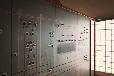
Anatomy of a High-Performance Industrial Control Panel
When analyzing a well-structured automation enclosure, organization is everything. A professional system features a centralized Siemens PLC rack driving arrayed motor controllers via high-speed communication or discrete I/O cabling.
As showcased in modern panel assemblies, the top layer focuses entirely on computational brains. The middle row transitions into signaling and protection, while the lower tiers manage high-current Variable Frequency Drives (VFDs) running the actual plant infrastructure.
Step 1: Strategic Component Segregation on the DIN Rail
The first phase of mastering panel layout is proper physical segregation. High-voltage hardware generates vast amounts of thermal energy and electromagnetic waves that can compromise delicate digital electronics.
Layout Hierarchy Guidelines:
The Logic Zone:
Keep your primary Siemens PLC CPU and expansion input/output cards on the absolute highest rail. This keeps them safe from rising heat.
The Intermediate Zone:
Place terminal blocks, terminal rails, and distribution links right below the processor.
The Power Zone:
Line up heavy motor drives along the bottom sections of the panel frame to maximize ambient cooling and shorten external cable runs.
Step 2: Implementing Interface Relays for Circuit Isolation
Directly connecting field devices to digital output modules can endanger your expensive processor. To safeguard the Siemens PLC system from unexpected overcurrent or inductive voltage spikes, an interface relay bank is essential.
Using a row of high-quality relays with visible LED indicators provides immediate optical feedback for diagnostics. This layout acts as an electrical firewall, isolating sensitive solid-state logic outputs from the high-power inductive circuits driving industrial contactors or solenoids.
Step 3: Mastering VFD Power and Control Cabling
Driving multiple independent motors requires dedicated Variable Frequency Drives, such as the robust INVT drive series. To maintain optimal speed control accuracy, you must treat your power and signal cables differently.
As demonstrated in professional engineering setups, run your 24V DC control connections through independent wiring ducts completely isolated from the heavy three-phase AC distribution wires.
Step 4: Suppressing Noise in Siemens PLC Systems
Electromagnetic interference (EMI) is the silent killer of factory automation loops. High-frequency switching inside VFDs inherently generates harmonic distortions that can disrupt data flow within the network.
To achieve flawless operation, always run shielded cables for motor outputs and bond the shield directly to the panel’s common grounding plate. Additionally, routing power supply wires through distinct physical pathways ensures your Siemens PLC remains totally immune to cross-talk or voltage sags.
Internal Link Reference
Step 5: Testing and Dynamic Parameter Optimization
The final step is methodical testing. Before turning on the high-power mains, power up your control transformer circuit first. Verify that the processor successfully initializes and reads all connected digital and analog inputs without raising any system faults.
Once the logic checks out, proceed to tune your acceleration, deceleration, and torque profiles directly on the drive interfaces to complete your commissioning routine.
Conclusion
Building a world-class industrial control panel requires a deep understanding of hardware behavior and neat execution. From tracking wire colors to arranging layout grids, every decision directly impacts long-term operational lifespan.
External Reference Resource:
If you want to step up your factory's production capabilities with tailored hardware layouts, explore our end-to-end automation engineering services at Nexify AutoMission today.