A VFD Braking Resistor plays an important role in applications where an AC motor needs to slow down quickly and safely. A Variable Frequency Drive controls motor speed by changing the frequency and voltage supplied to the motor. However, when a motor decelerates rapidly, it can return electrical energy toward the drive. As a result, the DC bus voltage inside the VFD can rise beyond its normal operating level.
A VFD Braking Resistor helps manage this excess energy during deceleration. Instead of allowing the energy to continue increasing the DC bus voltage, the braking system directs the energy toward a resistor. The resistor then converts the electrical energy into heat. Therefore, the VFD can reduce motor speed more effectively while keeping the DC bus voltage within an acceptable range.
Moreover, braking resistors become especially useful when a machine has high inertia or requires frequent stopping. For example, cranes, conveyors, hoists, centrifuges, elevators, and winding machines may need controlled and relatively fast deceleration. In such systems, the normal VFD deceleration function may not provide enough braking performance on its own.
This guide explains how a VFD Braking Resistor works, why a VFD may need one, how engineers approach resistor sizing, and where this braking method is commonly used. It also covers wiring concepts, operating considerations, troubleshooting, and important safety practices.
What Is a VFD Braking Resistor?
A VFD Braking Resistor is an electrical resistance device that absorbs excess energy produced when a motor decelerates through a VFD. During normal acceleration, the drive supplies energy to the motor. During certain deceleration conditions, however, the motor can act temporarily like a generator and send energy back toward the drive.
This returned energy increases the voltage of the VFD's DC link. If the voltage rises too far, the drive may trigger a DC-bus overvoltage fault. Consequently, the motor may stop decelerating as expected, and the machine can lose its required stopping performance.
The braking resistor provides a controlled path for this excess energy. A braking circuit detects the appropriate DC-bus condition and connects the resistor to the DC link. The resistor then dissipates the electrical energy as heat.
Therefore, the main purpose of the resistor is not simply to stop the motor. Instead, it helps the VFD handle regenerative energy during controlled deceleration.
Why Does a VFD Need Braking?
A VFD normally controls motor speed by adjusting the electrical output supplied to the motor. When the drive commands the motor to slow down, the motor's stored mechanical energy must go somewhere.
If the machine has very little rotating inertia, the drive may reduce speed without creating a major regeneration problem. However, high-inertia loads can behave differently. The rotating equipment continues moving because of its stored kinetic energy, even after the VFD starts reducing the output frequency.
As a result, the motor can return energy to the drive. The DC-link capacitors then receive this energy, which causes the DC-bus voltage to increase.
A VFD Braking Resistor helps control this situation by converting the excess electrical energy into heat. Consequently, the drive can achieve a more controlled deceleration without relying only on the motor's natural coast-down time.
How Regenerative Energy Develops During Deceleration
The relationship between motor speed and electrical energy becomes important when a machine decelerates. During normal motoring operation, electrical power flows from the VFD toward the motor. The motor converts that electrical power into mechanical power.
During rapid deceleration, the direction of energy flow can change. The mechanical system still contains kinetic energy, and the motor can convert part of that mechanical energy back into electrical energy.
That electrical energy travels toward the VFD's DC link. If the drive has no suitable method for managing the returned energy, the DC-bus voltage can continue rising.
Therefore, the braking system must provide a way to handle this energy. A braking resistor offers one practical solution for many industrial applications.
VFD Braking Resistor and DC-Bus Overvoltage
DC-bus overvoltage is one of the main reasons engineers consider dynamic braking. When the motor decelerates too aggressively, regenerative energy can increase the DC-link voltage faster than the VFD can naturally manage it.
The drive monitors its internal DC-bus voltage. If that voltage approaches the protection limit, the VFD can reduce or stop the deceleration process. In many cases, this results in an overvoltage fault.
A properly selected VFD Braking Resistor gives the braking circuit a controlled load for dissipating excess energy. Consequently, the system can handle short periods of regenerative power more effectively.
However, the resistor cannot solve every braking problem. Engineers must consider the motor, load inertia, stopping time, braking frequency, resistor resistance, power rating, and duty cycle before selecting a suitable unit.
Dynamic Braking vs. Normal Deceleration
Normal VFD deceleration and dynamic braking do not always provide the same performance. With normal deceleration, the drive reduces its output frequency according to the programmed ramp. The motor then slows down according to the available braking capability of the system.
Dynamic braking adds another method for handling regenerative energy. When the motor sends energy back into the DC link, a braking circuit can connect the resistor and dissipate that energy.
Therefore, dynamic braking becomes particularly useful when the application requires faster or more controlled stopping.
For example, a conveyor carrying a heavy load may need to stop within a specific time. Similarly, a hoist may require controlled speed reduction when lowering a load. In these situations, simply increasing the deceleration rate may cause a DC-bus overvoltage condition. A properly designed braking system can help manage the additional energy.
Where VFD Braking Resistors Are Commonly Used
A VFD Braking Resistor is most useful in machines where the load has significant inertia or where frequent deceleration occurs. The exact requirement depends on the mechanical characteristics of the application and the desired stopping performance.
Conveyors may use braking resistors when heavy material must stop quickly. Hoists and cranes can also require dynamic braking because their loads can create substantial mechanical energy during speed changes. Likewise, centrifuges can store considerable rotational energy because their rotating assemblies operate at high speed.
Elevators, winding machines, test stands, and certain machine tools can also benefit from dynamic braking. In each case, engineers evaluate the actual load behavior instead of selecting a resistor only from the motor's horsepower rating.
How Does a VFD Braking Resistor Work?
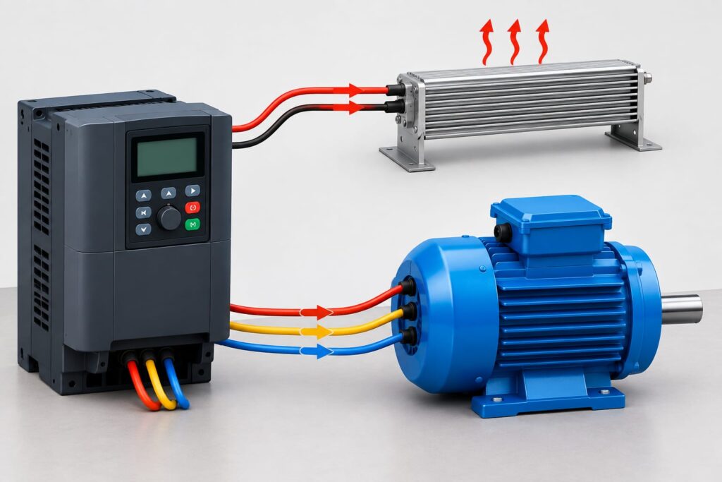
A VFD Braking Resistor works as part of a dynamic braking system that manages excess electrical energy during motor deceleration. To understand its operation, it helps to follow the energy path from the motor back toward the VFD. During normal operation, electrical energy moves from the drive to the motor. However, during certain deceleration conditions, the motor can send energy in the opposite direction.
The VFD detects changes in its DC-link voltage as this energy returns. If the voltage starts rising beyond the desired level, the braking circuit can connect the resistor to the DC bus. The resistor then converts the excess electrical energy into heat. As a result, the system can control the regenerative energy without allowing the DC-bus voltage to rise excessively.
Main Components of a VFD Braking System
A VFD Braking Resistor does not normally work alone. A complete dynamic braking arrangement can include the VFD DC bus, braking transistor or brake chopper, braking resistor, protection devices, and the motor itself. Each part performs a different function within the braking process.
The DC bus provides the electrical connection between the VFD's input conversion stage and output inverter stage. During regeneration, electrical energy can flow back toward this DC section. The braking transistor then controls when the resistor receives this energy.
The resistor provides the actual energy-dissipation path. Because electrical energy turns into heat inside the resistor, its construction must match the expected braking load. Therefore, engineers need to consider both the amount of energy and how frequently the machine produces it.
Role of the DC Bus During Braking
The DC bus plays a central role in dynamic braking. Inside a typical VFD, the incoming AC supply passes through a rectifier and creates a DC voltage. Capacitors then help smooth this DC voltage before the inverter section converts it into the controlled AC output required by the motor.
During normal operation, the DC bus remains within a suitable voltage range. However, when the motor decelerates and returns energy to the drive, the DC-bus voltage can increase.
If the returned energy exceeds the drive's ability to manage it, the voltage may approach the VFD's protection threshold. Consequently, the drive may generate an overvoltage fault or modify the deceleration process.
A VFD Braking Resistor provides an additional way to control this energy. The braking circuit uses the resistor to remove excess energy from the DC bus and convert it into heat.
How the Braking Transistor Controls Energy
The braking transistor, often called a brake chopper, acts like an electronic switch in the braking circuit. Its job is to control when the braking resistor connects to the DC bus.
When the DC-bus voltage reaches the programmed braking threshold, the control system can activate the braking transistor. This action allows current to flow through the resistor. The resistor then absorbs the available regenerative energy.
As the braking process continues, the control circuit manages the switching operation according to the DC-bus condition. Therefore, the resistor does not simply remain connected to the DC bus continuously during every operating condition.
This controlled switching also helps prevent unnecessary heating. The exact control method depends on the VFD design, braking unit, and manufacturer specifications.
Energy Flow Through a VFD Braking Resistor
Understanding energy flow makes the braking process easier to visualize. During acceleration, the VFD sends electrical energy toward the motor. The motor uses this energy to produce mechanical motion.
During deceleration, the situation can change. The moving load still contains mechanical energy, and the motor can convert some of that energy back into electrical energy.
That returned energy reaches the VFD's DC bus. If the voltage rises enough, the braking circuit activates and sends the excess energy through the VFD Braking Resistor.
The resistor converts the electrical energy into heat. Therefore, the energy path can be understood as:
Mechanical energy → Motor → DC bus → Braking circuit → Resistor → Heat
This process allows the VFD to control regenerative energy without sending that energy back to the AC supply.
What Happens When the Braking Resistor Is Undersized?
Correct resistor selection matters because a resistor must handle the energy produced during braking. An undersized VFD Braking Resistor may overheat if the machine produces more braking energy than the resistor can safely dissipate.
For example, a machine may stop correctly during the first few cycles but experience problems after repeated braking. The resistor temperature can continue increasing when the cooling period between braking events is too short.
As a result, engineers should not select a resistor simply by looking at motor horsepower. The application requires a proper assessment of braking energy, peak braking power, stopping time, braking frequency, and duty cycle.
The VFD manufacturer's specifications also matter because the drive may have minimum resistance and maximum braking-current limits.
What Happens When the Resistance Value Is Too Low?
Resistance value is another important consideration. A VFD Braking Resistor with resistance below the VFD's permitted minimum can allow excessive braking current to flow.
This condition can place additional stress on the braking transistor and other components. In severe cases, excessive current can damage the braking circuit.
Therefore, the selected resistance value should always remain within the VFD manufacturer's specified range. A lower resistance does not automatically mean better braking performance.
Instead, the braking system must balance resistance, braking current, power, energy, and thermal capacity.
What Happens When the Resistance Value Is Too High?
A resistance value that is too high can create the opposite problem. The braking circuit may not be able to draw enough current to remove regenerative energy quickly enough.
Consequently, the DC-bus voltage can continue rising during aggressive deceleration. The VFD may then experience an overvoltage condition before the braking system can provide sufficient energy dissipation.
For this reason, both extremely low and excessively high resistance values can create problems. Proper selection requires the resistor value to match the VFD's braking specifications and the actual machine requirements.
Why Braking Resistors Produce Heat
A VFD Braking Resistor converts electrical energy into thermal energy. This heat is a normal part of dynamic braking rather than a sign that the resistor has automatically failed.
However, excessive heat can become a problem when the resistor operates beyond its rated duty cycle. Frequent braking events can cause the resistor temperature to rise faster than it can release heat into the surrounding environment.
Therefore, ventilation, mounting location, ambient temperature, enclosure design, and duty cycle all matter. Engineers should also maintain adequate clearance around the resistor according to the manufacturer's instructions.
Braking Duty Cycle and Repeated Stops
The amount of braking energy is only one part of resistor selection. The frequency of braking events also affects thermal performance.
A machine that stops once every hour has very different braking requirements from a machine that accelerates and stops every few seconds. Even when both machines use motors with similar ratings, their braking systems can require very different resistor capacities.
For this reason, engineers consider the braking duty cycle when selecting a VFD Braking Resistor. They examine how often braking occurs, how long each braking event lasts, and how much energy the resistor must dissipate during each cycle.
This approach helps prevent overheating and improves the long-term reliability of the braking system.
When Is Dynamic Braking Actually Necessary?
Not every VFD installation needs a braking resistor. If a motor can decelerate naturally within the required time and the DC bus remains within its normal operating range, an additional braking resistor may not provide a significant benefit.
However, the situation changes when the application requires rapid stopping, frequent deceleration, or control over a high-inertia load.
For example, a heavy conveyor may need to stop within a short period. A centrifuge may store substantial rotational energy at high speed. Similarly, a hoist may require controlled braking during movement.
In these applications, a VFD Braking Resistor can provide an effective method for managing regenerative energy and supporting controlled deceleration.
Dynamic Braking Is Not the Same as Regenerative Braking
Dynamic braking and regenerative braking both deal with energy produced during motor deceleration, but they handle that energy differently.
With dynamic braking, the braking resistor converts the excess electrical energy into heat. The energy leaves the system through the resistor rather than returning to the electrical supply.
With regenerative braking, specialized equipment can transfer suitable regenerated energy back to the electrical network or another usable energy system.
Therefore, dynamic braking is often a practical choice when the main goal is controlled deceleration rather than energy recovery.
VFD Braking Resistor Sizing: What You Need to Know
Selecting the correct VFD Braking Resistor requires more than simply matching the resistor with the motor's horsepower. The braking system must handle the energy that the motor and load generate during deceleration. Therefore, engineers normally consider resistance value, braking power, braking energy, stopping time, frequency of braking events, and the required duty cycle.
A resistor that cannot handle the expected braking load may overheat or fail prematurely. On the other hand, selecting an unsuitable resistance value can place excessive current through the VFD's braking circuit. For this reason, proper sizing forms one of the most important steps in a reliable dynamic braking system.
How to Size a VFD Braking Resistor
Sizing a VFD Braking Resistor requires more than simply matching the resistor to the motor horsepower. The braking system must handle the energy produced during deceleration while staying within the VFD's electrical and thermal limits.
Engineers normally consider the motor speed, load inertia, required stopping time, braking frequency, DC-bus voltage, minimum resistance allowed by the VFD, peak braking power, and resistor duty cycle. Therefore, accurate sizing starts with understanding the actual machine rather than relying on a general resistor rating.
A resistor that is too small may overheat, while an unsuitable resistance value can create excessive braking current or insufficient braking performance. Consequently, proper sizing helps the complete braking system operate safely and reliably.
Important Factors in VFD Braking Resistor Sizing
The required VFD Braking Resistor depends heavily on how the machine operates. A motor that stops occasionally has different braking requirements from a motor that starts and stops repeatedly throughout the production cycle.
The required stopping time is also important. A shorter stopping time generally means the system must remove energy more quickly. As a result, the braking system may require higher peak power capacity.
Load inertia also affects the calculation. Heavy rotating equipment stores more kinetic energy than a lightly loaded system. Therefore, engineers should evaluate the mechanical load instead of selecting a resistor based only on the motor nameplate.
Finally, the VFD manufacturer's braking specifications should always guide the final selection. These specifications can define the permitted resistance range, maximum braking current, braking transistor capacity, and recommended resistor ratings.
Resistance Value and Braking Current
The resistance value directly affects the current that flows through the braking circuit. A lower resistance generally allows higher current, while a higher resistance limits the current.
However, the lowest possible resistance is not automatically the best choice. If the resistance falls below the VFD's specified minimum, the braking circuit may experience excessive current. This can place unnecessary stress on the braking transistor and other internal components.
On the other hand, a resistance value that is too high may not provide enough braking current to control the DC-bus voltage during rapid deceleration.
Therefore, the selected VFD Braking Resistor must stay within the resistance range specified by the VFD manufacturer.
Braking Power and Energy
Braking power describes how quickly the system must dissipate regenerative energy. During a rapid stop, the resistor may experience a high level of instantaneous power even if the average power over a longer period remains relatively low.
This difference matters because a resistor may have separate ratings for continuous power, short-duration power, and pulse energy.
For example, a machine could require high braking power for a few seconds but remain idle for several minutes afterward. In that situation, the resistor needs to tolerate the short high-power event and then release the accumulated heat during the cooling period.
Consequently, engineers should evaluate both peak braking power and average braking power when selecting a resistor.
Braking Duty Cycle
Duty cycle is another major factor in VFD Braking Resistor selection. It describes how frequently and for how long the braking resistor operates.
Consider two machines with identical motors. The first machine may stop once every ten minutes, while the second machine may stop every twenty seconds. Although their motors have the same rating, the second machine can generate much more frequent braking energy.
As a result, the second application may require a resistor with greater thermal capacity or a different duty rating.
Engineers should therefore calculate the braking pattern across the complete operating cycle. This approach provides a more realistic estimate of the resistor's thermal requirements.
Basic VFD Braking Resistor Wiring
A VFD Braking Resistor connects to the VFD's designated braking terminals or to an external braking unit, depending on the drive design. Some VFDs include an internal braking transistor, while others require an external braking module.
The exact terminals and wiring arrangement vary between manufacturers and VFD models. Therefore, installers should always follow the specific wiring diagram supplied with the drive.
The resistor should also have appropriate protection and mounting arrangements. Since it converts electrical energy into heat, the installation must provide sufficient clearance and ventilation.
Incorrect wiring can damage the braking circuit or create a serious electrical hazard. For that reason, technicians should never assume that braking terminals have the same arrangement across different VFD brands.
External Braking Units and Resistors
Some VFD systems use a separate braking unit instead of connecting the resistor directly to the drive. The external unit contains the switching electronics required to control the braking resistor.
This arrangement can provide additional flexibility for larger drives or applications that require significant braking power.
However, the external braking unit and resistor must work within their specified voltage, current, resistance, and thermal limits. Therefore, the complete system should be selected as a matched braking solution rather than treating each component as an independent device.
Common VFD Braking Resistor Problems
Even a correctly selected braking resistor can develop problems if the installation or operating conditions are unsuitable. Therefore, technicians should understand the symptoms of common braking issues.
One common problem is resistor overheating. This can occur when the braking frequency exceeds the expected duty cycle, when the resistor has insufficient ventilation, or when the application generates more energy than the selected resistor can handle.
Another issue involves incorrect resistance. A resistance value below the VFD's permitted minimum can increase braking current, while excessive resistance may reduce braking effectiveness.
A damaged braking transistor can also prevent the resistor from operating correctly. In addition, loose connections, damaged cables, poor ventilation, and incorrect VFD parameters can affect braking performance.
Troubleshooting VFD Braking Problems
When a VFD produces a DC-bus overvoltage fault during deceleration, the first step should be to understand the operating conditions rather than immediately replacing the resistor.
Check whether the programmed deceleration time is too short for the load. Next, verify the braking resistor's resistance value and inspect its physical condition. The wiring and braking terminals should also match the VFD manufacturer's diagram.
If the resistor becomes excessively hot, investigate the braking duty cycle and cooling conditions. Furthermore, check whether the machine has recently changed its load, speed, stopping frequency, or operating cycle.
If the problem continues, technicians should consult the VFD manufacturer's troubleshooting information and test the braking circuit using appropriate electrical procedures.
Safety Considerations for VFD Braking Resistors
Safety is especially important because a VFD Braking Resistor can reach high temperatures during operation. The resistor should remain away from combustible materials and should have adequate ventilation according to the manufacturer's installation requirements.
The VFD and braking circuit can also contain dangerous electrical energy even after the incoming power has been disconnected. Therefore, qualified personnel should follow the manufacturer's discharge time, isolation, and verification procedures before working on the equipment.
Never touch a braking resistor immediately after operation. Allow sufficient cooling time and verify that the equipment is safe to handle.
In addition, technicians should use suitable protective equipment and follow the electrical safety procedures required for the installation.
How to Improve VFD Braking Resistor Reliability
Proper selection provides the foundation for reliable braking, but installation and maintenance matter as well. The resistor should have enough thermal capacity for the actual braking duty cycle.
Good ventilation can also help prevent excessive temperature buildup. Therefore, the mounting location should allow heat to escape without exposing nearby components to unnecessary thermal stress.
Regular inspection can identify loose connections, damaged cables, discoloration, overheating marks, or other signs of abnormal operation. Moreover, technicians should monitor repeated VFD faults because they can reveal changes in machine behavior before a major failure occurs.
Most importantly, the braking system should remain within the electrical and thermal limits specified by the VFD and resistor manufacturers.
VFD Braking Resistor vs. Regenerative Drive
A VFD Braking Resistor dissipates excess regenerative energy as heat. A regenerative drive, in contrast, can transfer suitable regenerated energy back to the electrical supply or another energy system.
Dynamic braking can be a practical and relatively straightforward solution when the machine produces short periods of regenerative energy. However, applications that regenerate large amounts of energy continuously may benefit from an energy-recovery approach.
Therefore, the correct solution depends on the application's braking frequency, energy level, operating cycle, system architecture, and economic requirements.
Conclusion
A VFD Braking Resistor provides an effective way to manage excess regenerative energy when an AC motor decelerates. By converting this energy into heat, the braking system can help control DC-bus voltage and support faster, more controlled stopping.
However, successful braking depends on more than installing a resistor. The resistance value, braking power, energy capacity, duty cycle, cooling arrangement, wiring, and VFD specifications must all work together.
For that reason, engineers should evaluate the complete application before selecting a braking resistor. A conveyor, crane, centrifuge, elevator, or winding machine can each have very different braking requirements.
When the resistor matches the VFD and the machine's actual operating conditions, dynamic braking can improve stopping performance and help reduce unwanted DC-bus overvoltage problems. Most importantly, correct sizing, proper installation, adequate cooling, and safe maintenance help the braking system deliver reliable long-term performance.
In short, understanding how a VFD Braking Resistor works gives engineers and technicians a better foundation for designing, troubleshooting, and maintaining VFD-based motor control systems.

Pingback: VFD Overvoltage Fault: Causes, Diagnosis & Solutions