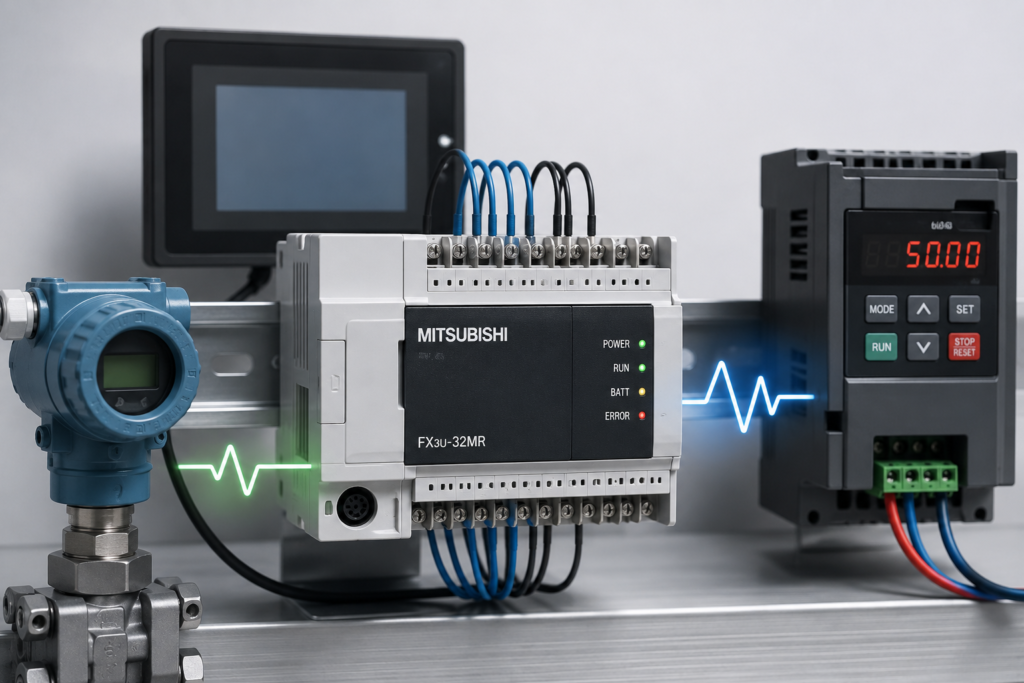
Mitsubishi FX PLC Modbus RTU communication provides a practical way to exchange data between an FX controller and external industrial devices over a serial network. Instead of treating the PLC as an isolated controller, Modbus RTU allows it to share process values, commands, and status information with devices such as drives, meters, temperature controllers, remote I/O units, and other compatible controllers. Because of that, understanding the communication process is useful when building a connected automation system.
In a typical factory installation, the PLC may need information from several devices at the same time. For example, a controller can request a measurement from an energy meter, send a reference value to a drive, or read operating status from another controller. Modbus RTU is well suited to these tasks because it uses a structured request-and-response method over a serial connection.
What Is Modbus RTU?
Modbus RTU is a serial communication protocol designed for exchanging data between electronic devices. The term RTU, or Remote Terminal Unit, refers to the compact binary message format used to transmit information. Compared with a text-based protocol, RTU sends data efficiently, which makes it suitable for industrial communication where reliable data transfer matters.
A Modbus RTU network normally contains one device that manages communication and one or more devices that respond to requests. In many applications, the Mitsubishi FX PLC works as the master, while a drive, meter, controller, or other field device works as a slave. The master starts a transaction, and the selected slave responds with the requested information or confirms that an instruction has been completed.
However, the role of the FX PLC does not always have to be identical in every installation. The required arrangement depends on the application, the selected FX hardware, and the communication method being used.
Why Use Modbus RTU With a Mitsubishi FX PLC?
One of the main advantages of Modbus RTU is that it creates a common communication method between devices from different manufacturers. A Mitsubishi FX PLC can therefore be connected to compatible equipment without requiring every device to use the same proprietary communication system.
This becomes especially useful when an automation project combines products from several vendors. A machine might use a Mitsubishi controller, a third-party power meter, a variable frequency drive from another manufacturer, and a separate temperature controller. Rather than creating a completely different communication strategy for each device, Modbus RTU can provide a consistent framework for exchanging data.
Another benefit is the relatively simple physical network. Depending on the selected interface and system design, RS-485 is commonly used for Modbus RTU because it supports multi-device serial communication and works well over industrial distances when the wiring and termination are handled correctly.
Most importantly, Modbus communication is based on clearly defined data transactions. That makes it easier to understand what the PLC is requesting, which device should answer, and what information should be returned.
Mitsubishi FX PLC Modbus RTU Communication Structure
Before configuring a Modbus network, it is important to understand how a transaction moves through the system.
Imagine an FX PLC needs to read a process value from an external controller. The PLC sends a Modbus request containing the address of the target device, the required function, and the relevant data location. The receiving device checks the request. If the message is valid and the requested information is available, that device sends a response back to the PLC.
The PLC then processes the returned data and can use it within the application.
This sequence may look simple, but each part matters. The device address must be correct. Communication settings must match on both ends. The requested register or data location must exist in the remote device. In addition, the received message must pass the required error checks before the PLC accepts it as valid information.
Consequently, a Modbus system should be viewed as a chain of coordinated elements rather than just a cable between two devices.
Master and Slave Roles
The terms master and slave describe the communication roles in a traditional Modbus RTU arrangement.
The master controls when communication takes place. It initiates a request and identifies which slave should respond. A slave does not normally begin an ordinary transaction on its own. Instead, it waits for a request that matches its address and then returns the appropriate response.
For example, consider a Mitsubishi FX PLC connected to a temperature controller. The PLC may send a request to read a process register. The temperature controller checks its own device address, locates the requested register, and returns the stored value. The PLC can then interpret that value and continue with the control sequence.
The same concept can work with several slaves on one serial network. The PLC sends a request to one address at a time, while the remaining devices stay silent until they are selected.
This role separation helps prevent multiple devices from responding simultaneously and keeps the communication process organized.
Understanding Device Addresses in FX PLC Modbus
Each slave needs its own address on an FX PLC Modbus network. The master uses this address to identify the device that should receive a request.
For example, a network may contain three slave devices. You could assign them addresses 1, 2, and 3. When the Mitsubishi FX PLC sends a request to address 2, that device handles the message and sends the response.
Correct addressing is essential for reliable FX PLC Modbus communication. A wrong address can make a healthy device appear offline. The wiring may be correct, and the PLC may still be running normally. However, the request will not reach the intended slave when its address is incorrect.
For that reason, always verify the slave address before investigating more complex communication issues.
Matching Communication Parameters
Successful FX PLC Modbus communication also requires compatible serial settings. Both devices must use the same communication parameters.
These settings can include the baud rate, parity, data bits, and stop bits. For instance, an FX PLC and a connected slave cannot exchange valid messages when they use different baud rates.
The same problem can occur when their parity or frame settings differ. Therefore, check the communication settings on both devices before testing the network.
The available options depend on the FX PLC model, communication interface, and connected equipment. Always compare the PLC configuration with the settings listed in the slave device manual.
How FX PLC Modbus Data Exchange Works
FX PLC Modbus communication uses defined requests and responses. The master sends a request, and the selected slave returns the requested information or confirms a write operation.
For example, an FX PLC may request a drive status value. It could also write a speed reference to a supported register. In another system, the PLC might read electrical measurements from a power meter.
Each request targets a specific type of data. The PLC therefore needs to know which function and data location the connected device supports.
Keep in mind that register numbers belong to the device that defines them. A register listed in a drive manual does not automatically have the same meaning in another manufacturer's device.
Before creating an FX PLC Modbus application, check the slave's register map carefully. This document tells you which addresses contain useful values and which locations accept written commands.
A clear register map makes configuration much easier and helps prevent incorrect data from entering the control system.
Building an FX PLC Modbus Communication Link
Once the device address and serial settings are correct, the next step is to establish a dependable communication path. A Mitsubishi FX PLC can exchange useful process data with drives, meters, controllers, and other compatible equipment, but every part of the connection must work together.
This is where FX PLC Modbus communication moves from a basic protocol concept to a practical industrial system. The physical interface, message settings, register map, and request sequence all have to agree before meaningful data can be exchanged.
RS-485 Connection for FX PLC Modbus
Many Modbus RTU installations use an RS-485 serial interface. Unlike a simple point-to-point connection, RS-485 can support multiple devices on the same communication bus when the network has been designed correctly.
The physical connection normally uses a pair of differential signal lines. The actual terminal names can vary between devices, so you should always check the wiring diagrams supplied with the PLC interface and the connected equipment.
A reliable connection also depends on good cable routing. Keep communication wiring away from sources of strong electrical interference where practical. Motors, contactors, variable frequency drives, and power cables can introduce unwanted noise into a poorly installed network.
For that reason, FX PLC Modbus installations should be wired with the same care given to other industrial communication systems.
Modbus RTU Network Topology
The physical arrangement of the network also affects communication quality. RS-485 networks generally work best when devices follow a suitable bus arrangement rather than using random branch connections.
Consider a system with one Mitsubishi FX PLC and three external devices. The communication line can pass along the network from one device to the next. Each device then uses its assigned Modbus address to identify its place in the logical communication system.
Long branch connections can create signal problems, particularly as network length and communication speed increase. Therefore, the wiring layout should follow the recommendations provided for the selected interface and equipment.
The goal is simple: give every device a clear and stable path for receiving and transmitting data.
Modbus Function Codes
After the physical connection works, the PLC needs to know what action it wants the slave to perform. Modbus uses function codes to define that action.
A read operation, for example, asks the slave to return information from a supported data area. A write operation instructs the slave to change a supported value.
Different devices support different functions. Therefore, you should never assume that every slave supports every Modbus command.
The slave manual normally identifies the available function codes and the related data areas. By checking this information first, you can build requests that match the capabilities of the connected device.
This approach makes FX PLC Modbus integration much more predictable because the PLC requests only information that the slave can actually provide.
Reading Data From a Modbus Slave
Reading is one of the most common tasks in a Modbus RTU application. The Mitsubishi FX PLC sends a request that identifies the target device and the required data location.
Suppose a PLC communicates with a power meter. The meter may provide voltage, current, frequency, or energy information through documented registers.
The PLC requests the required value and receives a response from the meter. It can then process that value for monitoring, logging, display, or control purposes.
However, the returned number may not always represent the final engineering value directly. A device might store a measurement using a scale factor. For example, a value of 253 could represent 25.3 units according to the manufacturer's register documentation.
Therefore, the PLC program must follow the scaling rules defined by the slave device.
Writing Data to a Modbus Device
Modbus can also allow the PLC to send values to a compatible slave. This feature becomes useful when the PLC needs to provide a command, reference, or configuration value.
For example, an FX PLC could send an operating reference to a drive when the drive supports the required Modbus write function. Another application might write a setpoint to a temperature controller.
The important part is to confirm that the destination register accepts writing. Some registers are read-only, while others may accept a specific range of values.
Before sending a write command, check the device manual for the register address, allowed range, data format, and required function. That simple step can prevent incorrect commands from reaching the equipment.
Register Mapping in FX PLC Modbus
Register mapping deserves special attention because different manufacturers organize their data differently.
A slave manual may provide a table containing register numbers, descriptions, data types, scaling information, and access permissions. This table acts as the communication map between the PLC and the device.
For example, one register may contain motor status, another may contain actual speed, while a different location may contain an operating reference. The PLC needs the correct location for each value.
It is also important to understand how the device represents numbers. Some data may use 16-bit values, while other parameters may require two consecutive registers. Signed and unsigned values can also produce different results when the PLC interprets the returned bytes.
Consequently, successful FX PLC Modbus communication depends on more than receiving a response. The PLC must also interpret that response correctly.
Handling Communication Responses
A master should not treat every received response as valid data automatically. The response needs to match the request and pass the relevant communication checks.
If the slave returns the expected data, the PLC can continue processing it. If the slave reports an exception or the expected response does not arrive, the program should handle that condition separately.
This distinction becomes especially important in industrial applications. A missing response should not silently become a zero value, because the control system might interpret zero as a genuine measurement.
Instead, the application can maintain a communication-status condition alongside the actual process value. That way, the operator can distinguish between zero data and missing data.
Communication Timeout and Retry Handling
Serial networks can experience temporary communication problems. Electrical noise, disconnected cables, overloaded devices, or incorrect timing can prevent a response from arriving within the expected period.
A well-designed FX PLC Modbus application should therefore account for communication timeouts.
When a request receives no response, the system can detect the timeout and apply an appropriate retry strategy. However, endless retries are not a good solution. Excessive requests can delay other communication tasks and make the network harder to diagnose.
A better approach uses controlled retries and a clear communication-failure state. If the problem continues, the PLC can flag the device as unavailable and allow the rest of the machine logic to respond safely.
Keeping Communication Data Separate From Machine Logic
Another useful design practice is to keep communication handling separate from the main machine sequence.
For example, communication routines can manage reading values, writing commands, checking status, and recording errors. The main application can then use the processed values without needing to manage every communication detail.
This separation improves clarity. It also makes future modifications easier because a change to one Modbus device does not necessarily require major changes throughout the machine program.
As a result, FX PLC Modbus communication becomes easier to maintain as the project grows.
Practical Example: FX PLC and a Variable Frequency Drive
Consider a small conveyor system using a Mitsubishi FX PLC and a compatible variable frequency drive.
The PLC needs to obtain the drive's operating status and send a speed reference. First, the communication interface is connected according to the equipment documentation. Next, both devices receive matching serial settings, and the drive receives its unique Modbus address.
The PLC then sends a read request for the drive status. After receiving valid data, the program checks the returned value and determines whether the drive is ready, running, or reporting a fault.
The PLC can then send a supported write request containing the required speed reference. The drive receives the command and applies it according to its own configuration.
In this arrangement, Modbus carries the information between the two devices while the PLC remains responsible for the overall machine sequence.
This example also shows why register mapping matters. The PLC cannot simply send an arbitrary number and expect the drive to understand it. The command, address, data format, and scaling must match the drive's documentation.
Preparing for Reliable Testing
Before placing an FX PLC Modbus system into full operation, test communication in controlled stages.
Start by verifying the physical connection. Then confirm the serial settings and device address. After that, test a simple read operation using a known register.
Once the read works reliably, test a single write operation when the connected device permits it. Finally, introduce the communication into the complete machine sequence.
This staged approach makes faults easier to locate. If a problem appears after adding the machine logic, you can separate the communication issue from the application logic instead of troubleshooting everything at once.
Testing and Troubleshooting FX PLC Modbus Communication
Once the communication link has been configured, the final step is to verify that data moves reliably in the real application. A network may appear correct on paper, yet small issues can still prevent the PLC and external device from communicating properly. For that reason, testing should be performed in a clear and controlled sequence.
Checking FX PLC Modbus Communication
Start with the physical connection. Inspect the communication cable, terminals, connectors, and power supply of the connected equipment. A loose terminal can create an intermittent problem that looks like a software fault.
Next, compare the communication settings on both devices. Confirm the baud rate, parity, data format, and stop bits. Also verify the slave address before testing requests.
Afterward, test one known data register. A simple read request is often easier to verify than a large group of commands. When the expected value appears correctly, you can gradually add more communication tasks.
Monitoring Communication Status
A reliable FX PLC Modbus application should distinguish between valid data and communication failure. The PLC can track whether a request received the expected response and whether the response contained usable information.
For example, a temperature value of zero may be a legitimate reading. However, zero should not automatically be used when the temperature controller stops responding.
A separate communication-status condition makes this distinction clearer. As a result, the machine can react correctly when a device becomes unavailable.
Common Wiring Problems
Communication faults often begin with the physical network. Incorrect terminal connections, damaged cables, poor shielding, or unsuitable routing can interfere with RS-485 communication.
Signal polarity also deserves attention. The names used for differential communication terminals can vary between manufacturers, so the wiring diagram for each device should be checked carefully.
In addition, electrical noise can affect long communication runs. Keeping communication cables away from high-power wiring can help reduce interference.
Incorrect Register Selection
Even when the network responds, the PLC may display the wrong information. One common reason is an incorrect register address.
The device manual should always be used to identify the correct data location. Also check whether the register contains a signed value, unsigned value, scaled measurement, or multi-register value.
For example, a drive may store speed using a specific scale factor. If the PLC interprets that number as a direct engineering value, the displayed result can become misleading.
Therefore, correct FX PLC Modbus communication requires correct data interpretation as well as successful message delivery.
Handling Communication Failures
A lost response should trigger a controlled reaction rather than an endless stream of requests. The PLC can allow a limited number of retries and then raise a communication fault when the problem continues.
This approach prevents one unavailable device from consuming all communication time. It also gives operators a clear indication that the external device needs attention.
The response to a communication failure should depend on the application. A monitoring system may simply display an alarm, while a machine controlling a critical process may need to move to a safer state.
Practical Commissioning Approach
During commissioning, test one device at a time whenever possible. Begin with basic communication, then verify individual reads and writes. Afterward, connect the communication logic to the wider machine sequence.
Keep a record of the device address, register information, communication settings, and expected values. This information becomes useful when the system needs maintenance later.
It is also helpful to compare transmitted and received data during troubleshooting. When the request looks correct but the response differs from expectations, the slave manual can often reveal the cause.
Best Practices for FX PLC Modbus
A good FX PLC Modbus project should use clear device documentation, consistent naming, controlled retries, and dedicated communication-status handling.
Avoid sending unnecessary requests. Read only the information the application actually needs, and organize related values where practical. This keeps communication easier to understand and helps reduce unnecessary network traffic.
Most importantly, document every connected device. Record its address, supported functions, register map, scaling rules, and communication parameters. Good documentation can save considerable time when the system is expanded or repaired.
FAQs About FX PLC Modbus
Can a Mitsubishi FX PLC communicate with Modbus RTU devices?
Yes. A compatible Mitsubishi FX PLC communication interface can exchange Modbus RTU data with supported external devices. The exact method depends on the FX model, communication hardware, and device configuration.
What is the role of the PLC in an FX PLC Modbus network?
In a common Modbus RTU arrangement, the PLC works as the master. It sends requests to slave devices and processes their responses. However, the required role depends on the selected hardware and application.
Why does my FX PLC Modbus connection fail even when the wiring is correct?
Several settings can cause this problem. Check the slave address, baud rate, parity, data format, stop bits, and register information. Also verify that both devices support the requested Modbus function.
How do I find the correct Modbus register?
Use the register map provided by the device manufacturer. It normally identifies the address, data type, scaling, access permission, and purpose of each supported register.
Can one Mitsubishi FX PLC communicate with multiple Modbus devices?
Yes. A suitable RS-485 Modbus RTU network can connect multiple compatible devices. Each slave must have an appropriate unique address so the PLC can communicate with the intended device.
What should I check when Modbus data is incorrect?
First, verify the register address and data type. Then check scaling, signed or unsigned interpretation, word order where applicable, and the function used to read the data. A successful response does not always mean the PLC has interpreted the returned value correctly.
Conclusion
FX PLC Modbus provides a practical way to connect a Mitsubishi FX controller with compatible industrial devices and exchange useful process data. The communication becomes reliable when the physical connection, serial parameters, device addresses, function codes, and register mapping all match the requirements of the connected equipment.
More importantly, successful communication is not only about getting a response from a slave. The PLC must also verify that the response is valid and interpret the returned information correctly. By testing the network step by step and documenting the device settings, you can make the system easier to commission, maintain, and expand.
With the right configuration, Modbus RTU can provide a straightforward communication layer for drives, meters, controllers, and other equipment in an industrial automation system.