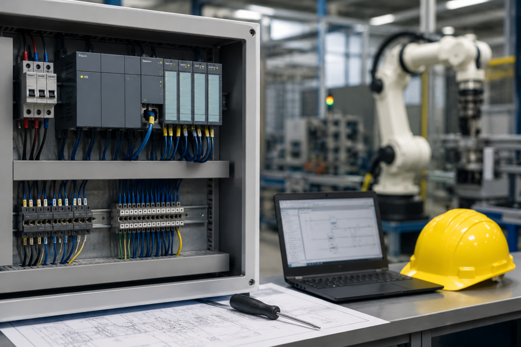
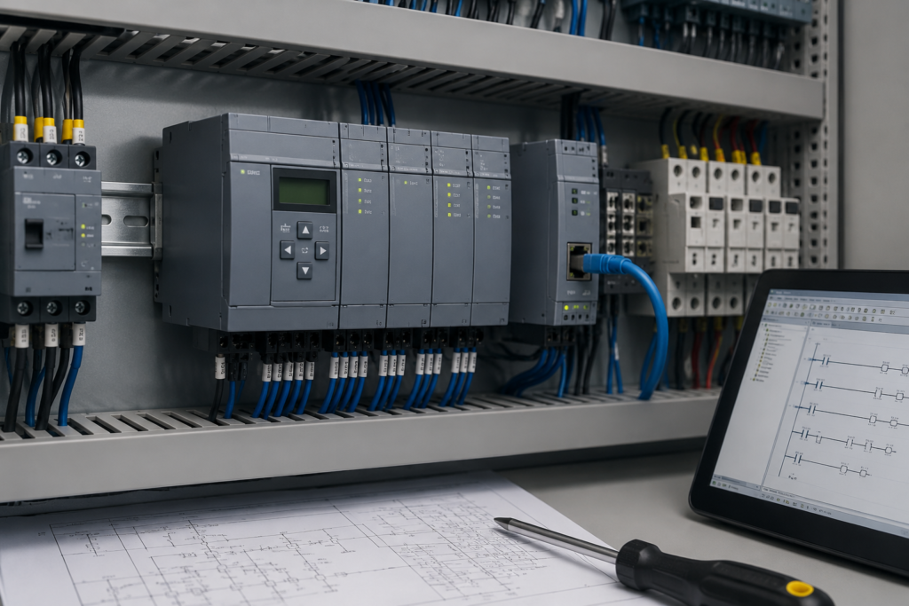
Table of Contents
ToggleIntroduction
A PLC Troubleshooting Guide is one of the most valuable resources for anyone working with industrial automation systems. Programmable Logic Controllers (PLCs) control machines, production lines, and automated processes in factories around the world. When a PLC system develops a fault, production may stop, equipment performance may decrease, and maintenance costs can increase. Learning how to troubleshoot PLC problems correctly helps engineers and technicians identify the real cause of an issue and restore normal operation quickly.
PLC troubleshooting is more than replacing faulty hardware. A successful troubleshooting process requires logical thinking, careful inspection, and a clear understanding of how PLC hardware and software work together. Many common PLC faults are caused by loose wiring, damaged sensors, incorrect programming, communication failures, power supply problems, or input and output device issues. Identifying these problems early reduces downtime and improves system reliability.
This PLC Troubleshooting Guide explains the most common PLC problems and provides practical solutions that beginners and experienced professionals can follow. You will learn how to diagnose faults safely, understand PLC status indicators, check inputs and outputs, verify communication, and apply preventive maintenance practices. By following these methods, you can reduce unexpected machine failures and keep industrial automation systems operating efficiently.
Whether you work with Siemens, Allen-Bradley, Mitsubishi, Omron, Delta, Schneider Electric, or another PLC brand, the troubleshooting principles discussed in this guide remain similar. Although software interfaces may differ, the process of identifying and correcting faults follows the same logical approach.
By the end of this article, you will understand how to troubleshoot PLC systems with confidence and improve the reliability of industrial automation equipment.
What Is PLC Troubleshooting?
PLC troubleshooting is the process of identifying, diagnosing, and correcting faults in a Programmable Logic Controller system. The objective is to restore normal machine operation while reducing downtime and preventing future failures.
A PLC system consists of several important components that work together. These include:
- CPU
- Power supply
- Input modules
- Output modules
- Communication modules
- Sensors
- Actuators
- Human Machine Interface (HMI)
- Industrial network cables
If any of these components stop working correctly, the PLC may generate alarms, stop processing logic, or fail to control machinery properly.
Effective troubleshooting follows a structured approach instead of guessing. Replacing random components wastes both time and money. A professional technician first gathers information, checks indicators, identifies the faulty area, and then verifies the repair.
Why PLC Troubleshooting Is Important
Modern industries depend on automation for productivity and consistent product quality. Even a small PLC fault can stop an entire production line.
A proper PLC Troubleshooting Guide helps maintenance teams:
- Reduce machine downtime.
- Improve production efficiency.
- Increase equipment reliability.
- Minimize maintenance costs.
- Improve worker safety.
- Prevent repeated failures.
- Extend equipment life.
- Improve troubleshooting skills.
Without a systematic troubleshooting process, small faults can become expensive equipment failures.
For example, a loose communication cable may appear to be a PLC CPU failure. Replacing the CPU without checking the cable wastes money and does not solve the actual problem.
Common Causes of PLC Failures
Understanding common PLC failures makes troubleshooting much faster.
1. Power Supply Failure
A damaged or unstable power supply prevents the PLC from operating correctly.
Common causes include:
- Voltage fluctuations
- Blown fuse
- Loose wiring
- Power overload
- Failed power supply module
Typical symptoms include:
- PLC completely off
- Power LED off
- Random PLC restart
- Unexpected shutdown
2. Faulty Inputs
Input devices provide information to the PLC.
Common input devices include:
- Push buttons
- Limit switches
- Proximity sensors
- Photoelectric sensors
- Pressure switches
- Float switches
When an input device fails, the PLC receives incorrect information.
Possible causes:
- Broken sensor
- Damaged wiring
- Incorrect voltage
- Dirty sensor surface
- Loose terminal connection
3. Output Failures
Outputs control external devices.
Examples include:
- Motors
- Solenoid valves
- Contactors
- Indicator lamps
- Buzzers
- Relays
If an output module fails, machines may not respond correctly.
Possible reasons:
- Burned relay
- Short circuit
- Output overload
- Wiring fault
- Damaged output module
4. Communication Problems
Many industrial automation systems use communication networks between PLCs, HMIs, drives, and SCADA systems.
Communication failures may occur because of:
- Broken Ethernet cable
- Network configuration errors
- Faulty communication module
- Electrical interference
Common symptoms include:
- HMI offline
- SCADA disconnect
- Network timeout
- Lost PLC connection
5. Programming Errors
Not every PLC problem is caused by hardware.
Sometimes the PLC program itself creates unexpected machine behavior.
Programming mistakes include:
- Incorrect timer values
- Wrong counter settings
- Missing interlocks
- Duplicate outputs
- Incorrect logic sequence
- Wrong memory address
- Improper data handling
Testing the program before installation greatly reduces programming-related failures.
Power Supply Problems and Solutions
Power problems are one of the most common reasons for PLC failures. Therefore, checking the power supply should always be your first step. A stable power source keeps the PLC CPU, input modules, and output modules working correctly. Even a small voltage issue can stop an entire production line.
A good PLC Troubleshooting Guide always starts with the power supply because many machine faults are linked to unstable or missing power.
Common Signs of Power Supply Failure
Look for these warning signs:
- The PLC does not turn on.
- The Power LED remains off.
- The PLC restarts again and again.
- The CPU suddenly enters fault mode.
- The HMI loses connection with the PLC.
- Outputs stop working without warning.
These symptoms often indicate a power-related problem. However, you should confirm the cause before replacing any component.
Common Causes
Power supply problems usually occur because of:
- Low input voltage
- High input voltage
- Loose power terminals
- Damaged power cables
- Blown fuse
- Failed power supply module
- Short circuit in the control panel
How to Check the Power Supply
Follow these simple steps.
Step 1: Check the Main Power
First, verify that the incoming power is available. Then inspect the circuit breaker and fuse.
Step 2: Measure the Voltage
Next, use a digital multimeter to measure the PLC input voltage.
Compare the reading with the manufacturer's recommended value.
Step 3: Inspect the Wiring
After that, inspect every terminal carefully.
Look for:
- Loose wires
- Burn marks
- Corrosion
- Broken insulation
A loose terminal can interrupt the power supply even when the voltage is correct.
Step 4: Check the Power LED
Most PLCs include a Power LED.
If the LED is off, the PLC may not be receiving power.
If the LED flashes, consult the PLC manual because different brands use different LED patterns.
Step 5: Replace Faulty Parts
Finally, replace damaged fuses, cables, or power supply modules if testing confirms they are faulty.
Never replace parts without testing first.
Understanding PLC Status LEDs
Modern PLCs provide useful diagnostic information through LED indicators.
Therefore, learning LED meanings can save a lot of troubleshooting time.
A PLC Troubleshooting Guide always recommends checking LEDs before connecting software or replacing hardware.
Common PLC LEDs
Most PLCs include:
- Power LED
- Run LED
- Fault LED
- Error LED
- Communication LED
- Input LEDs
- Output LEDs
Each LED provides important information about the PLC condition.
Power LED
A green Power LED normally means the PLC is receiving power correctly.
If the LED is off, inspect the power supply immediately.
Run LED
A green Run LED shows that the PLC program is running normally.
If this LED is off, the CPU may be in Stop mode.
Fault LED
A red Fault LED usually indicates a serious problem.
Possible causes include:
- CPU fault
- Memory error
- Program error
- Hardware failure
Do not ignore this indicator.
Instead, connect the programming software and read the diagnostic messages.
Communication LED
This LED shows network activity.
If it does not blink during communication, inspect:
- Ethernet cable
- Communication settings
- IP address
- Network switch
- Communication module
Input Device Troubleshooting
Input devices send signals to the PLC.
If an input fails, the PLC cannot make the correct decision.
Therefore, checking sensors should be part of every PLC Troubleshooting Guide.
Common Input Devices
Industrial systems commonly use:
- Push buttons
- Limit switches
- Proximity sensors
- Photoelectric sensors
- Pressure switches
- Float switches
- Temperature sensors
Common Input Problems
Input faults usually include:
- Sensor failure
- Broken cable
- Loose wiring
- Incorrect voltage
- Dirty sensing surface
- Incorrect installation
Troubleshooting Steps
First, observe the input LED.
If the sensor is active but the LED remains off, inspect the wiring.
Next, measure the input voltage.
Then verify the sensor output using a multimeter.
Finally, replace the sensor only if testing confirms it is defective.
This method saves both time and maintenance costs.
Output Device Troubleshooting
Output modules control industrial equipment.
Therefore, output failures directly affect machine operation.
Examples include:
- Motors
- Solenoid valves
- Relays
- Contactors
- Alarm lamps
- Buzzers
Common Output Problems
Output failures may occur because of:
- Burned relay
- Damaged transistor output
- Short circuit
- Loose wiring
- Overloaded output channel
Troubleshooting Procedure
First, check whether the output LED turns on.
If the LED remains off, inspect the PLC logic.
However, if the LED is on but the device does not operate, inspect the wiring and field device.
Next, measure the output voltage.
Compare the measured value with the equipment specification.
Finally, inspect the relay or contactor coil.
Many output problems are caused by field devices instead of the PLC itself.
Following this logical process makes troubleshooting faster and more accurate.
PLC Troubleshooting Guide for Communication Problems
Communication problems are common in industrial automation. However, most of them are easy to fix. A good PLC Troubleshooting Guide always begins with simple checks. First, inspect the communication cable. Then, verify the network settings. After that, review the PLC status. This method saves both time and effort.
The following issues appear frequently:
- PLC is offline.
- HMI cannot communicate with the PLC.
- SCADA displays communication errors.
- Ethernet network disconnects randomly.
- Data updates stop unexpectedly.
- Devices respond very slowly.
Although these problems look serious, many of them have simple solutions.
PLC Troubleshooting Guide: Check Communication Connections
First, inspect every communication cable carefully. Look for loose connectors, broken insulation, damaged pins, or bent plugs. Even a small cable fault can stop communication. Therefore, replace any damaged cable before checking other components.
Next, inspect the communication ports. Dust or moisture inside a connector may interrupt the signal. In addition, make sure every connector is fully locked into place.
PLC Troubleshooting Guide: Verify Network Settings
After checking the cables, review the network settings. Compare the PLC IP address with the HMI or SCADA settings. Also, verify the subnet mask and gateway. If one value is incorrect, communication may fail immediately.
Moreover, confirm that every device uses the correct communication protocol. Different protocols cannot exchange data unless they are configured correctly.
PLC Troubleshooting Guide: Inspect Communication LEDs
Now inspect the communication LEDs. Normally, blinking LEDs show active data transfer. However, if the LEDs remain off, inspect the communication module and the network switch.
Sometimes a simple restart restores communication. Therefore, restart the PLC and connected devices after completing the inspection.
Restart Communication Devices
Sometimes communication stops because of temporary software errors.
Therefore, restart the PLC, HMI, or network switch if all wiring appears normal.
PLC Troubleshooting Guide for CPU Faults
The CPU controls the entire PLC system. Therefore, a CPU fault should never be ignored. Fortunately, many CPU problems can be identified within a few minutes.
Common CPU Fault Symptoms
Watch for these signs:
- Red Fault LED
- PLC stops running
- Program does not execute
- Unexpected restart
- Diagnostic alarms
These symptoms usually indicate a hardware or software issue.
Check Diagnostic Messages
First, connect the PLC programming software.
Then read the diagnostic buffer.
The error message often identifies the exact problem.
Inspect Memory Status
Next, verify that the PLC memory is healthy.
Memory corruption can prevent the PLC from starting correctly.
If necessary, reload the backup program.
Verify Firmware
In addition, check the firmware version.
An incorrect firmware version may create compatibility problems after maintenance.
An incorrect firmware version may create compatibility problems after maintenance.
PLC Troubleshooting Guide for Preventive Maintenance
Preventive maintenance is one of the best ways to reduce unexpected PLC failures. Instead of waiting for a machine to stop, maintenance teams should inspect the system regularly. As a result, small problems can be corrected before they become expensive breakdowns. A complete PLC Troubleshooting Guide always recommends preventive maintenance because it improves reliability and reduces production downtime.
During routine maintenance, technicians should inspect the control panel carefully. They should verify that all wiring connections remain tight and clean. In addition, they should check for dust, moisture, corrosion, and overheating. These simple inspections often reveal problems before they affect production. Furthermore, cooling fans and ventilation filters should remain clean because excessive heat can shorten the life of PLC components.
Software maintenance is equally important. Therefore, every PLC program should have an updated backup. Whenever program changes are made, the backup should also be updated. Moreover, engineers should document every modification because accurate records make future troubleshooting much easier. If a fault appears later, the maintenance team can compare the latest program with the previous version and identify the cause quickly.
PLC Troubleshooting Guide for Faster Fault Diagnosis
A logical troubleshooting method saves both time and money. Therefore, technicians should avoid replacing parts without testing them first. Instead, they should collect information, inspect the PLC indicators, review diagnostic messages, and confirm every measurement before making a repair.
For example, a machine may stop because of a faulty proximity sensor. However, replacing the PLC CPU would not solve the problem. Likewise, a communication failure may simply be caused by a loose Ethernet cable instead of a defective communication module. As a result, following a structured troubleshooting process reduces unnecessary maintenance costs.
For example, a machine may stop because of a faulty proximity sensor. However, replacing the PLC CPU would not solve the problem. Likewise, a communication failure may simply be caused by a loose Ethernet cable instead of a defective communication module. As a result, following a structured troubleshooting process reduces unnecessary maintenance costs.
Moreover, technicians should always repair one fault at a time. If several changes are made together, it becomes difficult to identify the real cause of the problem. Therefore, every repair should be tested before another adjustment is made. This simple habit increases troubleshooting accuracy and improves maintenance quality.
PLC Troubleshooting Guide Expert Recommendations
Every industrial machine is different. However, the troubleshooting process should always remain simple and organized. A technician who follows a clear method usually finds the problem faster. Therefore, avoid making random changes inside the PLC program. Instead, collect information before taking any action.
Before starting any repair, observe how the machine behaves. Sometimes the fault appears only during a specific operating condition. For example, a conveyor may stop only when the production speed increases. In that case, the problem may not be the PLC itself. Instead, the issue could be a faulty sensor or an overloaded motor. Consequently, careful observation often saves valuable maintenance time.
Furthermore, technicians should compare the current machine condition with normal operation. If a new error appears after maintenance, review the most recent changes first. In many situations, the latest modification explains the new fault. Therefore, keeping accurate maintenance records is extremely helpful.
Another useful practice is checking one section of the machine at a time. For example, verify the power supply first. Next, inspect the input devices. After that, examine the output devices. Then, review communication settings. Finally, inspect the PLC program. This step-by-step approach reduces confusion and prevents unnecessary repairs.
Moreover, every maintenance team should create a regular inspection schedule. Dust, vibration, heat, and moisture slowly damage electrical components. Although these problems develop gradually, they can eventually cause unexpected machine failures. Therefore, routine inspections should never be ignored.
In addition, always use high-quality spare parts. Low-quality components may fail quickly and create repeated maintenance problems. As a result, reliable replacement parts usually reduce long-term operating costs.
Similarly, software backups should always remain up to date. Before changing the PLC program, create a backup copy. If something goes wrong, the previous version can be restored immediately. Consequently, production downtime remains much shorter.
Finally, continuous learning is an important part of industrial automation. PLC technology continues to improve every year. Therefore, technicians should regularly study new programming methods, communication protocols, and diagnostic tools. Better knowledge leads to faster troubleshooting and more reliable automation systems.
PLC Troubleshooting Guide Frequently Asked Questions
What is the first step in a PLC Troubleshooting Guide?
The first step is always checking the power supply. After that, inspect the PLC status LEDs and review any diagnostic messages. Finally, verify the wiring and field devices before replacing hardware.
Can PLC software cause machine failures?
Yes. Incorrect timers, counters, addresses, or logic conditions can create unexpected machine behavior. Therefore, software should always be checked together with the hardware.
Why does a PLC enter fault mode?
A PLC may enter fault mode because of hardware failure, memory errors, communication problems, incorrect programming, or unstable power. However, the exact reason can usually be found in the PLC diagnostic buffer.
How can communication problems be prevented?
Communication problems can be reduced by using quality network cables, maintaining correct IP settings, protecting cables from electrical noise, and inspecting communication modules regularly.
Why is preventive maintenance important?
Preventive maintenance reduces unexpected failures, improves equipment reliability, extends component life, and lowers maintenance costs. As a result, production becomes more stable and efficient.