In modern industrial automation, mastering the Siemens S7-300 PLC architecture is essential for any logic engineer or automation professional. Whether you are setting up hardware configurations in TIA Portal or diagnosing critical system faults on the shop floor, having a solid grasp of modular systems ensures minimal downtime.
This comprehensive guide breaks down 31 essential technical questions and answers. These will help you optimize your control panels, eliminate engineering errors, and achieve complete system reliability.
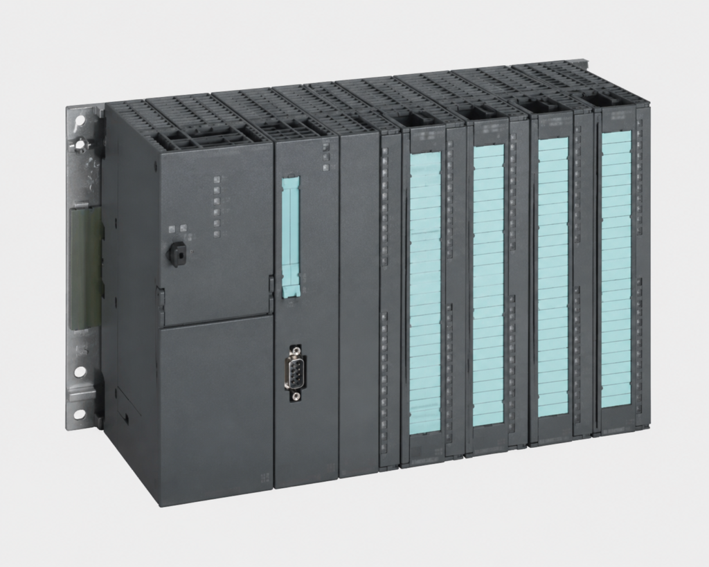
Q1: What is the purpose of the module labeled "SITOP" on the far left of the panel?
This is a Siemens SITOP Power Supply. Its purpose is to convert incoming AC utility voltage (230V/400V) into a stable 24V DC output to safely power the PLC CPU, I/O modules, and field control devices.
Q2: Based on the picture, does this Siemens PLC fall under the Compact or Modular category?
This is a modular system. The Power Supply, CPU, and Signal Modules are separate physical components that can be scaled and expanded based on system requirements.
Q3: What is the name of the metal rail on which these hardware modules are mounted?
It is called the Siemens S7-300 PLC DIN Rail (or Mounting Rail). Unlike standard top-hat DIN rails, it features a proprietary bolt-on design engineered specifically to secure this specific hardware series.
Q4: In the hardware configuration, which specific slot is always reserved for the Power Supply (PS)?
Slot 1 is strictly reserved for the Power Supply (PS) module in the rack configuration.
Q5: In TIA Portal or STEP 7 Hardware Configuration, which modules occupy Slot 2 and Slot 3?
Slot 2 is always reserved for the CPU, and Slot 3 is reserved for the Interface Module (IM). If no expansion rack is used, Slot 3 is left logically empty.
Q6: What is the maximum number of Signal Modules (SM) that can be installed on a single central rack?
A single rack can accommodate a maximum of 8 Signal Modules (SM), Function Modules (FM), or Communication Processors (CP), spanning from Slot 4 to Slot 11.
Q7: If a project requires more than 8 modules, what hardware is required to connect additional racks?
An Interface Module (such as IM 360/361 or IM 365) must be installed to bridge the data bus between the central rack and expansion racks.
Q8: How is data transferred between adjacent hardware modules along the backplane?
Data transfer is handled via Backplane Bus Connectors (U-Connectors) snapped onto the rear of each module, linking them together to form the internal bus communication path.
2. Wiring Standards, Signals, and Power Distribution
Proper wiring eliminates electromagnetic faults and preserves signal integrity across your industrial automation network.
Q9: According to industrial automation wiring standards, what type of signal does the blue wiring in the panel typically represent?
Blue wiring is standard for 24V DC Control Circuits (both Inputs and Outputs). In specific safety architectures, it can also denote intrinsically safe circuits for hazardous areas.
Q10: What is the technical name for the removable front block where all the control wires are terminated into the module?
It is called the Front Connector (available in 20-pin or 40-pin variants). It allows for rapid module replacement without needing to disconnect individual wires.
Q11: What are the gray slotted plastic channels installed above and below the modules called, and what is their purpose?
These are called Wire Ducts (or Cable Trunking). They are utilized to neatly route, organize, protect, and isolate control wiring inside the panel enclosure.
Q12: In industrial control panels, what circuits are typically assigned to Red and Yellow wires?
Red wires are generally used for AC control circuits (110V/230V AC). Yellow wires are reserved for safety interlock loops or external voltages that remain energized even when the main panel isolator is switched off.
Q13: What is the structural benefit of having short-circuit and overload protection built into the SITOP power supply?
If a field sensor or actuator shorts out, the SITOP power supply automatically trips or enters current-limiting mode. This isolates the fault and prevents catastrophic overcurrent damage to expensive PLC components.
Q14: Why is it a bad engineering practice to route Analog Signal wires (e.g., 4-20mA) in the same wire duct as high-voltage Digital I/O lines over long distances?
The rapid switching of digital signals induces Electromagnetic Interference (EMI) or electrical noise into adjacent wires, which distorts sensitive analog readings and causes fluctuating process data.
3. Addressing and TIA Portal Software Configuration
Accurate software addressing maps the physical world to your logic code. Let's look at how the engineering software interacts with your hardware.
Q15: If a Digital Input module's start address is configured as byte IB 0, what will be the absolute addresses of its first four inputs?
The absolute addresses will be I 0.0, I 0.1, I 0.2, and I 0.3..
Q16: What is the core difference between the data processed by a Digital Input (DI) module versus an Analog Input (AI) module?
A DI module processes binary discrete signals (0 or 1 / ON or OFF). An AI module processes continuous physical variables (like temperature or pressure) and translates them into a scalable integer value (0 to 27648 in Siemens systems).
Q17: Which state must the PLC CPU be in when compiling and downloading a modified Hardware Configuration from TIA Portal?
The CPU must enter STOP Mode to safely overwrite the hardware profile and initialize the newly mapped modules.
Q18: What is the operational difference between "Upload from Device" and "Download to Device" in Siemens software?
Download transfers the program and configuration files from the engineering laptop into the PLC memory. Upload extracts the existing program blocks and configurations from the physical PLC back to the laptop for backup or diagnostics.
Q19: What are the primary trade-offs between a Transistor-type Digital Output module and a Relay-type Digital Output module?
Transistor outputs switch exclusively DC loads, offer extremely high-speed switching frequencies, and have an almost infinite lifespan. Relay outputs can switch both AC/DC loads and handle higher currents, but have slower response times and suffer from mechanical wear over time.
Q20: If the "SF" (System Fault) Red LED illuminates on a CPU, what is your immediate first step for troubleshooting?
Connect to the PLC via TIA Portal/STEP 7 and open the Diagnostic Buffer. The SF LED indicates a severe hardware failure or software execution error, and the buffer logs the exact error code and affected block.
Q21: What does a solid or blinking Red "BF" (Bus Fault) LED indicate on the CPU?
It signals a network communication failure across the fieldbus (Profibus or Profinet). Common causes include severed network cables, unpowered remote drops, or unconfigured network addresses.
Q22: If an I/O module fails during production, can it be replaced while the system remains powered up?
Q23: If all indicator LEDs on a single Digital Input module are completely dead while the rest of the PLC system functions normally, what should you physically check?
Verify the Front Connector wiring to ensure that the 24V DC auxiliary power supply (typically wired to terminals L+ and M) is present and check for blown terminal fuses.
Q24: What does the "BATF" LED signify on a Siemens CPU, and what happens if the main panel power is cycled while it is active?
"BATF" stands for Battery Fault, indicating the backup battery is dead or missing. If main power is cycled while this is active, the volatile Work Memory (RAM) will clear, potentially wiping out unbacked-up program blocks and retaining data.
Q25: What is the structural role of Organization Block 1 (OB1) in a Siemens user program?
OB1 is the Main Cyclic Program Block. The operating system executes it continuously in a sequential loop (Scan Cycle), processing logic inputs and updating outputs non-stop.
Q26: If a field-mounted PT100 temperature sensor suffers a wire break, what raw value will the Analog Input module register?
The module will output an Overflow value of 7FFF (Hexadecimal) or 32767 (Decimal), allowing programmers to execute safety interlocks based on sensor failure logic.
Q27: If a module shows a Red Cross (X) inside the online TIA Portal hardware diagnostics but is physically present in the panel, what is the likely issue?
There is an asset mismatch. The physical module's part number (MLFB) or firmware version does not match the exact hardware configuration compiled in the software project, or the backplane bus connector is loose.
Q28: What is the operational purpose of the Watchdog Timer (WDT) in automated control systems?
The WDT monitors the execution time of the scan cycle. If the program gets trapped in an infinite loop and exceeds the pre-configured cycle limit (default is typically 150ms), the WDT forces the CPU into STOP mode to prevent dangerous, unmanaged machine states.
Q29: Why is it critical to tie the control panel's copper ground bar directly to the PLC mounting rail and the SITOP frame?
Direct grounding provides a low-impedance path to dissipate static charges, stray voltage surges, and high-frequency switching noise, preventing erratic CPU faults and random communication packet drops.
Q30: What function does the MRES switch perform on an S7-300 CPU chassis?
The MRES (Memory Reset) switch performs a master clear of the CPU work memory, resets the operating status, and reloads data from the Micro Memory Card (MMC) to resolve severe system blocks or memory conflicts.
Q31: Looking at the high-density wiring in the panel, if you need to add hundreds of field devices hundreds of meters away, what design choice eliminates heavy copper wiring expenses?
Implement a Distributed I/O System (such as the ET 200M). You position the remote I/O rack close to the distant field devices and tie it back to the main CPU using a single Profibus or Profinet fieldbus cable, slashing installation costs.
Conclusion & Next Steps