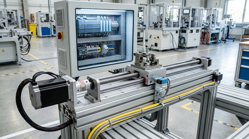
Modern industrial machines need accurate movement to place, align, feed, or adjust components at specific locations. For these tasks, stepper motor positioning offers a practical way to control motion with predictable movement and precise command signals. Manufacturers use stepper-based systems in equipment that needs repeatable positioning without the complexity or cost of some advanced motion systems.
A stepper motor divides rotation into controlled steps. A suitable driver receives command pulses and energizes the motor windings in a specific sequence. As a result, the motor moves through defined angular positions. The controller can then coordinate this movement with other machine functions to achieve a required position.
However, accurate positioning depends on more than the motor itself. The driver, controller, mechanical transmission, load, acceleration profile, and operating speed all affect the final result. Therefore, engineers need to evaluate the complete motion system rather than selecting a motor based only on its rated torque.
What Is Stepper Motor Positioning?
Stepper motor positioning means controlling a motor so that a machine component moves to a defined location. The controller sends movement commands, while the stepper driver converts those commands into electrical signals that operate the motor.
Unlike a motor that simply runs continuously, a stepper system provides controlled incremental movement. Each command advances the motor by a specific step. Consequently, the connected mechanical system can move to different positions according to the number and timing of those commands.
This approach works especially well when a machine needs repeated point-to-point movement. For example, an automated mechanism may move a carriage to several fixed locations during every production cycle. The control system can command each position in sequence without requiring a complex feedback arrangement for basic applications.
Why Positioning Matters in Industrial Automation
Industrial automation relies on consistent machine movement. A small positioning error can affect product alignment, material placement, cutting operations, inspection points, or assembly sequences. Therefore, motion control plays an important role in overall machine performance.
Stepper motors can provide a straightforward solution for applications that need controlled and repeatable movement. Their digital control characteristics also make them convenient to integrate with PLCs, motion controllers, and other automation equipment.
Moreover, stepper systems can hold a position when the application requires stationary force. This characteristic helps certain machines maintain the location of a mechanism during an operation. However, engineers must consider the available holding capability and the actual mechanical load before relying on this behavior.
How a Stepper Positioning System Works
A typical positioning system contains several coordinated components. The controller generates movement commands according to the machine program. Next, the stepper driver interprets those commands and supplies the required current to the motor windings.
The motor converts electrical energy into controlled rotational movement. From there, a mechanical transmission transfers that rotation to the machine mechanism. Depending on the design, engineers may use a lead screw, belt, rack-and-pinion system, or another mechanical arrangement.
For example, consider an automated linear carriage. The controller commands the carriage to move from one location to another. The driver operates the stepper motor, and the motor rotates the mechanical drive. The drive then moves the carriage along its rail.
The control sequence continues as the machine performs its programmed operation. Therefore, the final positioning result depends on the interaction between electrical control and mechanical movement.
Open-Loop Positioning
Many stepper motor systems use open-loop control. In this arrangement, the controller sends movement commands without continuously measuring the actual motor position through an encoder.
This design can simplify the system because it reduces feedback hardware and associated control complexity. As a result, engineers can build economical positioning systems for suitable loads and operating conditions.
However, open-loop operation has an important limitation. If the motor cannot produce enough torque to follow the commanded movement, it may lose synchronization with the command sequence. The controller may continue sending commands even though the mechanical system no longer occupies the expected position.
For that reason, engineers should not treat stepper motor positioning as automatically accurate under every condition. Proper motor sizing, acceleration control, load assessment, and mechanical design remain essential.
Accuracy and Repeatability
Accuracy and repeatability describe different aspects of positioning performance.
Accuracy describes how closely the machine reaches the intended position. Repeatability describes how consistently the machine returns to the same position during repeated movements.
A system can show good repeatability while still missing the exact target position by a small amount. Therefore, engineers should identify the actual machine requirement before selecting the motor and positioning method.
Mechanical factors also influence these characteristics. Backlash, coupling flexibility, screw quality, bearing condition, and structural movement can introduce errors even when the stepper motor receives correct commands.
Consequently, improving positioning performance often requires attention to the entire mechanical system rather than changing the motor alone.
Positioning Methods for Industrial Machines
Industrial machines use different positioning methods depending on the movement they need to perform. A stepper motor can support rotary positioning directly or drive a mechanism that creates controlled linear movement.
Rotary positioning works well when a machine needs to rotate a shaft, indexing table, reel, or adjustment mechanism to defined locations. The control system can command a sequence of movements according to the machine cycle.
Linear positioning creates another useful option. In this arrangement, the motor drives a mechanical transmission that moves a carriage, slide, or actuator along a fixed path. This setup suits equipment that needs controlled travel between multiple points.
The important consideration lies in matching the positioning method with the machine's mechanical design. A motor may perform well in one mechanism yet deliver poor results in another because friction, backlash, inertia, or mechanical flexibility can change the movement response.
Step-and-Direction Control
Many industrial positioning systems use a step-and-direction interface. One signal tells the driver to advance the motor, while another determines the direction of movement.
This approach keeps the control structure relatively straightforward. A PLC or motion controller can generate the required command signals while the dedicated driver handles motor current and phase control.
For multi-axis equipment, the same principle can extend to several motors. Each axis can receive its own commands, allowing the machine to coordinate movement across different mechanical sections.
However, command generation alone does not guarantee good positioning. The controller needs suitable acceleration and deceleration profiles so the motor can follow the requested movement without losing synchronization.
The Hidden Role of Acceleration
Acceleration often receives less attention than final position, yet it strongly affects positioning performance.
A sudden command for high-speed movement can place a large demand on the motor and mechanical system. If the motor cannot follow that demand, movement may become unstable or the system may lose synchronization.
A controlled acceleration profile gives the motor time to build speed. Likewise, gradual deceleration helps the mechanism approach its target without excessive mechanical disturbance.
This detail becomes particularly important in machines with frequent starts and stops. An application may appear to require only a modest final position, but repeated rapid movements can create demanding operating conditions.
Mechanical Backlash and Positioning Performance
The mechanical transmission can introduce an error that the motor itself cannot correct. Backlash provides a common example.
When a mechanism changes direction, clearance between mechanical components can create a small amount of movement before the driven part responds fully. Consequently, the commanded position and actual position may differ.
Lead screws, gear systems, couplings, and other transmission components can all influence this behavior. Regular mechanical inspection therefore matters just as much as electrical configuration.
A useful engineering approach involves evaluating the complete motion chain. Start with the motor shaft, then consider the coupling, transmission, bearings, and final moving element. This process helps identify where positioning errors may originate.
Positioning in Indexing Systems
Linear actuators give stepper motor positioning systems a practical way to move machine components along a defined path. Engineers can use this arrangement for automated slides, adjustment mechanisms, inspection fixtures, and controlled material movement.
The stepper motor generates rotary motion, while the actuator mechanism converts that rotation into linear travel. As a result, the control system can move a component between programmed locations along a machine axis.
However, the motor represents only one part of the positioning chain. The screw or transmission, coupling, bearings, guide system, and moving load can all influence how accurately the mechanism reaches its target.
A rigid mechanical structure can help maintain stable movement. Likewise, proper alignment and a suitable coupling can reduce unwanted motion. On the other hand, mechanical looseness can undermine precise commands even when the electrical control system works correctly.
Sensor-Assisted Positioning
Sensors can add another layer of reliability to stepper motor positioning systems. Instead of relying entirely on commanded movement, the machine can use sensor signals to identify important mechanical conditions.
Limit switches can indicate the end of travel, while home sensors can establish a reference point during machine startup. In addition, position or proximity sensors can confirm that a mechanism has reached a required location.
This approach gives the control system useful information about the machine's physical state. The stepper motor still performs the commanded movement, while sensors help the controller make informed decisions.
For instance, an automated slide can move toward its home sensor during startup. After the sensor detects the reference position, the controller can establish the machine's working coordinates and begin the programmed sequence.
Sensor integration does not automatically create closed-loop servo control. Instead, it provides reference, confirmation, and protection functions around the motion system.
An Often-Missed Design Consideration
A key point in stepper motor positioning involves the difference between commanded resolution and useful machine resolution.
The controller may command extremely small movement increments. Nevertheless, the physical mechanism may not reproduce every increment with the same practical precision.
Mechanical backlash, friction, structural flexibility, coupling movement, and transmission quality can all affect the final result. Therefore, engineers should evaluate the complete motion assembly instead of focusing only on the number of commanded steps.
This distinction can prevent an expensive design mistake. A system with highly detailed electronic commands may still deliver inconsistent physical movement if its mechanical components cannot support that level of performance.
Positioning Reliability During Real Production
Real production conditions can challenge stepper motor positioning in ways that laboratory or unloaded tests may not reveal. Changes in load, friction, temperature, operating speed, and cycle frequency can alter machine behavior.
Therefore, engineers should test the positioning system under conditions that closely match actual production. The evaluation should include the expected load, movement frequency, acceleration profile, and operating environment.
Furthermore, repeated-cycle testing can reveal gradual problems that a short test may miss. Increasing vibration, inconsistent stopping, unusual mechanical noise, or position drift can point toward developing mechanical or control issues.
For reliable operation, engineers should treat positioning as a complete system rather than a motor-only function. This approach helps maintain consistent movement as the machine moves from initial testing into continuous industrial production.
Factors That Affect Positioning Performance
Several factors can influence stepper motor positioning once a machine enters real operating conditions. Motor selection matters, but the surrounding mechanical and control components can have an equally important effect.
Load Characteristics
The connected load determines how much effort the motor needs during movement. A light mechanism may move smoothly with modest motor capacity, while a heavier assembly can demand significantly more torque during acceleration and direction changes.
Load behavior also matters. A mechanism with changing resistance can produce different results throughout a machine cycle. Therefore, engineers should evaluate the complete operating range instead of testing the system at only one load condition.
Operating Speed
Stepper motors do not produce the same performance across their entire speed range. As rotational speed increases, the available torque generally decreases. Consequently, a machine that performs well at low speed may struggle when the application demands faster movement.
Engineers should evaluate the motor's speed-torque characteristics before finalizing the design. This step helps establish a realistic operating range and reduces the risk of synchronization problems during production.
Resonance and Vibration
Certain operating ranges can produce unwanted vibration in stepper motor systems. Mechanical resonance can make the motor noisy, reduce smoothness, and affect the behavior of connected components.
The machine structure can influence this effect as well. Flexible mounting, poorly aligned couplings, or unsuitable mechanical loads may amplify vibration.
Therefore, engineers should consider the complete assembly when they encounter unusual vibration. Changing the operating speed, improving mechanical rigidity, or selecting an appropriate drive configuration can sometimes improve system behavior.
Choosing the Right Drive Configuration
The stepper driver plays a major role in how smoothly a motor responds to positioning commands. It controls the current supplied to the motor windings and determines how the motor responds to command signals.
A suitable driver should match the motor's electrical requirements and the controller's interface. In addition, engineers should consider the required operating speed, current capability, protection features, and installation environment.
For demanding industrial equipment, a driver with appropriate control features can help manage vibration and improve movement quality. However, the driver cannot compensate for an incorrectly sized motor or a poorly designed mechanical system.
This is why engineers should treat the motor and driver as a matched pair rather than selecting each component independently.
When Stepper Motor Positioning Makes Sense
Stepper motor positioning works particularly well when a machine needs controlled movement at moderate speeds, predictable indexing, or repeated movement between defined locations.
Cost can also influence the decision. A stepper-based system may offer a practical solution when the application does not require the full capabilities of a high-performance servo system.
Furthermore, stepper systems can simplify certain machine designs because they can operate without continuous position feedback. This characteristic suits applications where the load remains predictable and the machine can tolerate the limitations of open-loop operation.
However, engineers should avoid using a stepper system simply because the application needs movement. The required speed, acceleration, load behavior, precision, and fault response should determine the final technology choice.
When Another Motion Technology May Be Better
Some machines demand characteristics that make another motion solution more appropriate. High-speed applications, rapidly changing loads, demanding dynamic performance, or applications that require continuous position verification may benefit from servo technology.
A servo system can use feedback to compare commanded movement with actual shaft or load position. The controller can then adjust motor behavior according to the measured result.
This does not make servo systems automatically better for every application. They can introduce additional hardware, configuration requirements, and system complexity.
The correct approach involves matching the motion technology to the machine requirement. A well-sized stepper system can provide excellent results when its operating conditions remain within suitable limits.
Thermal Considerations
Temperature can also affect long-running positioning equipment. Stepper motors may draw current while holding a position, which can generate heat even when the shaft does not rotate.
Excessive heat can shorten component life and create an unfavorable machine environment. Therefore, engineers should consider motor current, duty cycle, enclosure conditions, ambient temperature, and available cooling.
Proper thermal management becomes especially important inside compact control cabinets or enclosed machinery. Adequate ventilation and correct driver settings can help maintain stable operating conditions.
Commissioning a Positioning System
Commissioning provides an important opportunity to verify whether the complete system performs as expected.
Engineers should first confirm correct wiring, mechanical alignment, travel limits, and controller configuration. After that, they can test movement at low speed before gradually introducing normal operating conditions.
The initial tests should focus on smooth movement and correct direction. Next, the team can evaluate acceleration, stopping behavior, target positions, and repeated cycles.
Any unexpected vibration, missed movement, mechanical noise, or inconsistent stopping deserves investigation before production begins.
A structured commissioning process can reveal problems early and prevent minor configuration issues from becoming production failures.
Maintenance Considerations
Reliable positioning also depends on the condition of the mechanical system. Wear in couplings, guides, bearings, screws, or other transmission components can gradually change machine behavior.
Regular inspection helps identify these changes before they create serious positioning problems. Maintenance teams should pay attention to unusual noise, increased vibration, loose connections, and changes in movement consistency.
Electrical connections also deserve attention. Loose terminals or damaged cables can interrupt motor operation and create intermittent faults that are difficult to diagnose.
As a result, preventive maintenance should cover both the motion hardware and the mechanical assembly connected to it.
A Practical Engineering Insight
One useful principle often gets overlooked: the machine's required positioning performance should come before the motor specification.
Instead of starting with a motor model, engineers should first define the required travel, load, speed, cycle frequency, environmental conditions, and acceptable positioning behavior. They can then select the motor, driver, transmission, and controller around those requirements.
This approach reduces over-sizing and under-sizing problems. More importantly, it keeps the motion system aligned with the actual production task rather than with a single component's specification.
For industrial machines, successful positioning comes from this complete-system mindset. The motor provides the motion, but the surrounding design determines how effectively the machine uses it.
Frequently Asked Questions
What is stepper motor positioning?
Stepper motor positioning controls a machine mechanism so it moves to defined locations. A controller sends movement commands to the driver, which then operates the motor according to those commands.
Where do industries use stepper motor positioning?
Industries use it in automated slides, indexing equipment, inspection mechanisms, adjustment systems, material-handling machines, and other equipment that needs controlled movement.
Can a stepper motor provide accurate positioning?
Yes, a properly designed system can provide accurate and repeatable movement. However, mechanical backlash, load changes, vibration, and operating speed can affect the final positioning result.
Do stepper motors require position sensors?
Not always. Many systems operate without continuous feedback. However, home sensors, limit switches, and other sensors can provide useful reference and machine-state information.
Can a PLC control a stepper motor?
Yes. A suitable PLC can send movement commands through compatible outputs or motion-control functions. The PLC can also coordinate positioning with sensors, interlocks, and other machine operations.
What causes positioning problems in stepper systems?
Common causes include excessive load, unsuitable acceleration, high operating speed, mechanical backlash, vibration, poor alignment, and incorrect motor or driver selection.
Are stepper motors suitable for every automation application?
No. They work well for many controlled-motion tasks, but demanding high-speed or continuously feedback-dependent applications may require another motion technology.
How can engineers improve positioning reliability?
Engineers can improve reliability by matching the motor and driver to the application, maintaining the mechanical transmission, using suitable acceleration profiles, testing realistic loads, and monitoring the system during production.
Conclusion
Stepper motor positioning provides a practical approach to controlled movement in many industrial automation systems. Its simple command structure, predictable incremental movement, and flexible integration make it suitable for indexing, linear motion, automated slides, and other positioning tasks.
However, reliable performance depends on the complete machine design. Motor selection, driver configuration, mechanical transmission, load behavior, acceleration, vibration, and operating conditions all influence the final result.
Therefore, engineers should evaluate the complete motion system before choosing components. With suitable sizing, proper commissioning, and regular maintenance, a stepper-based positioning system can deliver consistent performance for many industrial applications.