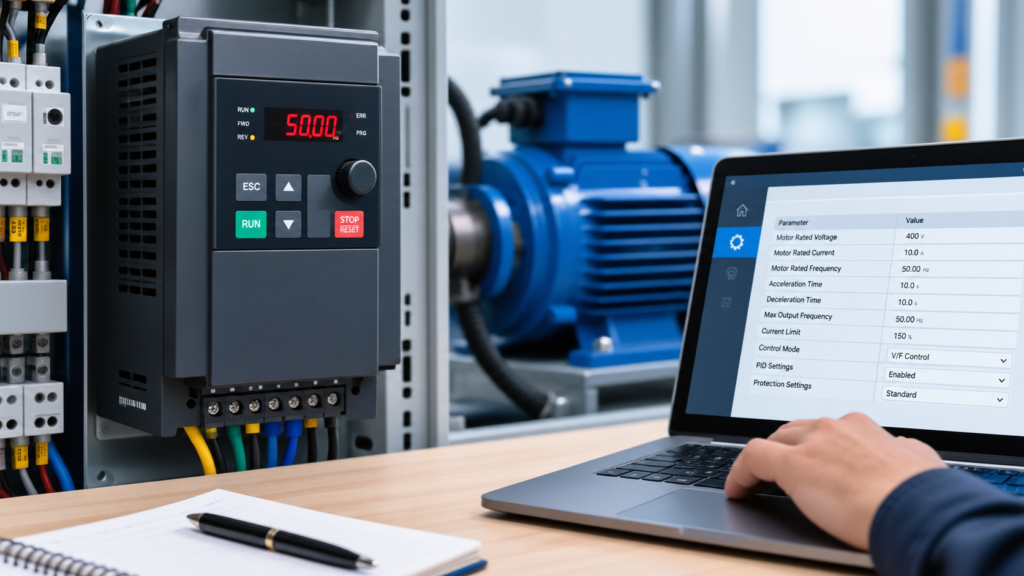
A variable frequency drive (VFD) gives engineers better control over motor speed, acceleration, and overall operation. However, the drive cannot perform correctly unless its parameters match the connected motor and application. Incorrect values may cause unstable operation, unnecessary trips, poor motor performance, or even equipment damage.
Proper VFD Parameter Settings help the drive communicate correctly with the motor and respond according to the machine's requirements. These settings are normally entered during commissioning, but they may also need adjustment when the motor, load, or operating conditions change.
Why Correct VFD Settings Matter
Every motor has specific electrical and operating characteristics. The VFD uses this information to control the motor safely and efficiently. Therefore, basic motor information should be entered before other control parameters are adjusted.
The motor nameplate should be checked first. Important information includes rated voltage, rated current, frequency, speed, and power. These values are then entered into the appropriate drive parameters. As a result, the VFD can establish suitable operating limits for the motor.
Incorrect data can create several problems. For example, the motor may draw excessive current, accelerate poorly, run hotter than expected, or produce unstable torque. In addition, incorrect protection values can prevent the drive from responding properly when an abnormal condition occurs.
VFD Parameter Settings for Motor Configuration
Motor configuration is one of the most important stages of VFD commissioning. The rated motor voltage should match the supply requirements specified on the motor nameplate. Similarly, the rated current should be entered accurately because the drive uses this value for motor protection and current control.
The rated frequency is also important. Most industrial motors are designed for a specific frequency, and the VFD uses this value as a reference for normal operation. The motor's rated speed may also be required, especially when the drive uses sensorless vector control or other advanced control methods.
Some VFDs provide an automatic motor identification or auto-tuning function. During this process, the drive analyzes motor characteristics and adjusts internal control values. The procedure should be performed according to the manufacturer's instructions because the motor may need to be stopped or safely isolated from the machine load.
Once the basic motor information has been entered, the drive can be configured for the required control method. Depending on the application, users may select simple V/F control, sensorless vector control, or another available mode. The correct choice depends on the required torque, speed accuracy, and application.
Setting Frequency and Speed Limits
Frequency limits determine how far the motor can be operated within the configured range. A minimum frequency can prevent the motor from running below a level that may provide poor cooling or insufficient torque. On the other hand, a maximum frequency can prevent the motor from being operated beyond its intended speed.
These limits should be selected according to the motor, mechanical system, and machine requirements. A higher frequency should not be used simply because the VFD allows it. Mechanical components may have their own speed limitations, and excessive speed can increase vibration or mechanical stress.
The frequency reference can also be configured according to the application. Depending on the VFD model, the reference may come from a keypad, analog input, digital control system, PLC, or communication network. The selected source should match the way the machine is intended to operate.
Acceleration and Deceleration in VFD Parameter Settings
Acceleration and deceleration times control how quickly a motor starts and stops. These values play an important role in VFD Parameter Settings because sudden speed changes can create mechanical stress, high current demand, or unstable machine movement.
A short acceleration time makes the motor reach its target speed quickly. However, the motor may require more current during this process. If the value is too aggressive, the VFD can trip on overcurrent. Therefore, the acceleration time should match the motor size and the machine's load.
Deceleration needs similar attention. When a VFD slows an induction motor, the motor can return energy toward the drive's DC bus. A very short deceleration time may raise the DC bus voltage and cause an overvoltage fault. For this reason, heavy or high-inertia machines often need a longer deceleration period.
VFD Parameter Settings for Control Mode
The control mode determines how the VFD manages motor speed and torque. Basic applications often work well with V/F control because it provides simple and reliable speed control. More demanding applications may require sensorless vector control when the machine needs stronger torque and better speed regulation.
Before selecting a control mode, consider the machine's actual requirements. A conveyor, pump, fan, and high-inertia machine may need different control characteristics. Choosing a more advanced mode does not automatically improve every application.
Many modern drives also provide motor identification or auto-tuning. This process helps the drive determine motor characteristics for better control. The technician should follow the manufacturer's procedure and ensure that the motor and machine remain in a safe condition during tuning.
VFD Parameter Settings for Start and Stop Control
Start and stop commands determine how the motor responds when the operator or control system sends a command. Depending on the application, the VFD may accept commands from its keypad, digital inputs, PLC, or communication network.
The selected command source should match the machine's control architecture. For example, a PLC-controlled system may use digital signals or industrial communication, while a simple standalone machine may use the drive's keypad or terminal inputs.
Stop behavior also matters. Some applications require a controlled ramp stop, while others may need freewheel stopping. The correct option depends on the machine and its safety requirements. A controlled stop can provide smoother operation, while freewheel stopping allows the motor to coast naturally.
VFD Parameter Settings for Current and Motor Protection
Current-related settings help protect both the motor and the drive. The rated motor current should come directly from the motor nameplate rather than from an estimate. This value gives the VFD a useful reference for its protection functions.
Current limits can also affect machine performance. If the limit is too low, the motor may struggle to produce the required torque. If it is too high, the drive may allow excessive current for longer than the motor can safely tolerate.
Thermal protection should also receive attention. Motors that operate at low speed for extended periods may receive less cooling because their cooling fan rotates more slowly. Therefore, the application may require additional cooling or a suitable motor designed for variable-speed operation.
Checking VFD Parameter Settings After Configuration
After entering the required values, the technician should test the motor at a safe and controlled speed. Observe acceleration, running current, motor direction, vibration, temperature, and overall machine response.
If the motor behaves normally, the technician can gradually test higher operating speeds within the machine's approved limits. Any unusual noise, excessive current, unstable speed, or unexpected fault should be investigated before normal operation continues.
Finally, record the configured values for future maintenance. Good documentation makes troubleshooting easier and helps technicians restore the correct configuration if the VFD needs replacement or reprogramming.
VFD Parameter Settings for PID Control
PID control is useful when a machine must maintain a process variable automatically. For example, pumps may need to maintain pressure, while fans may need to maintain airflow. In these applications, VFD Parameter Settings can be configured so the drive adjusts motor speed according to feedback from the process.
A typical PID system uses a setpoint, a feedback signal, and a control output. The setpoint represents the desired condition, while the sensor provides actual process information. The VFD then changes motor speed to reduce the difference between these two values.
PID settings should be adjusted carefully because aggressive values can make the motor speed fluctuate. On the other hand, very slow settings may cause the system to respond poorly to changes in demand. Therefore, the technician should tune the parameters according to the machine's response rather than simply copying values from another installation.
VFD Parameter Settings for Analog Inputs
Analog inputs allow a VFD to receive variable signals from devices such as potentiometers, pressure sensors, temperature controllers, or PLC systems. Common signal ranges include voltage and current signals, depending on the drive and control system.
The input range must be configured correctly within the VFD Parameter Settings. For example, if a controller provides a current-based reference, the drive should be configured for the matching input type. Otherwise, the motor speed may not respond correctly to the control signal.
Scaling also deserves attention. The drive needs to understand what the incoming signal represents. A properly scaled input can translate a sensor signal into a useful frequency or process value. Consequently, correct scaling helps the machine respond smoothly across its operating range.
VFD Parameter Settings for Digital Inputs
Digital inputs provide simple ON/OFF commands to the drive. These inputs can be assigned to functions such as start, stop, forward, reverse, reset, preset speed, or external fault.
The exact function assigned to each input depends on the application. Before changing these VFD Parameter Settings, the control wiring should be checked carefully. An incorrect assignment can cause an unexpected start command or prevent the motor from responding to the intended control signal.
For safety-related applications, the control system should also follow the appropriate machine safety design. A normal digital input should not automatically be treated as a dedicated safety function unless the drive and system have been specifically designed and certified for that purpose.
VFD Parameter Settings for Energy Efficiency
Energy efficiency can also be improved through appropriate drive configuration. Pumps and fans, for example, often operate at different speeds depending on demand. Reducing motor speed when full output is not required can significantly change the energy consumed by the system.
However, efficiency should not be pursued by simply lowering the frequency. The machine still needs enough speed and torque to perform its intended task. Therefore, VFD Parameter Settings should be selected according to actual process requirements.
Some drives include energy-saving functions that automatically adjust motor operation under suitable load conditions. These features may be useful, but they should be tested carefully because their effectiveness depends on the motor and application.
VFD Parameter Settings for Troubleshooting
When a VFD develops a fault, its stored parameters can provide valuable information. A technician should first compare the current configuration with the motor nameplate and the documented machine settings.
For example, incorrect motor current, frequency limits, acceleration time, or control-source settings can create operating problems. Similarly, an incorrect input configuration may make the drive appear faulty when the real problem exists in the control signal.
A parameter backup should therefore be maintained whenever possible. If the drive needs to be replaced, the documented VFD Parameter Settings can make commissioning faster and reduce the chance of configuration errors.
VFD Parameter Settings for Carrier Frequency
VFD Parameter Settings mein carrier frequency ek important setting hoti hai jo motor ke switching behavior ko affect karti hai. Is setting ka direct relation motor noise, drive heating aur overall operating behavior se ho sakta hai. Therefore, carrier frequency ko sirf noise kam karne ke liye unnecessarily high nahi karna chahiye.
A higher carrier frequency can make motor operation quieter, which may be useful in applications where acoustic noise matters. However, switching losses can also increase, and the drive may produce more heat. For this reason, the recommended value should always be considered according to the VFD manufacturer and application requirements.
Different motors and drives can respond differently to carrier frequency changes. Moreover, a setting that works well on one machine may not provide the same result on another. Therefore, the parameter should be adjusted gradually while monitoring motor temperature, drive temperature and operating stability.
Choosing the Right Switching Frequency
The switching frequency should be selected according to the motor, VFD capacity and application. If the frequency is increased too much, additional heat may be generated inside the drive. As a result, the drive may require better cooling or reduced load depending on the manufacturer's specifications.
On the other hand, a lower switching frequency can reduce switching losses and may help control drive temperature. However, motor noise can become more noticeable. Therefore, the best setting is usually a practical balance between noise, temperature and performance.
The final value should be checked during actual operation rather than selected only from theoretical expectations. If the motor runs smoothly and temperatures remain within acceptable limits, the selected setting can usually be retained.
VFD Parameter Settings for Torque Boost
VFD Parameter Settings can also include torque boost when additional low-speed motor torque is required. Torque boost increases the voltage available to the motor at low frequencies, which can help certain loads start or operate more effectively.
However, too much torque boost should be avoided. Excessive boost can increase motor current and heating, while efficiency may decrease. Therefore, torque boost should be increased gradually rather than using a high value immediately.
The correct approach depends on the motor and load characteristics. For example, a conveyor with a heavy starting load may require different settings from a lightly loaded fan. Consequently, the parameter should be evaluated during controlled testing.
Adjusting Low-Speed Motor Response
Low-speed operation can sometimes become unstable when the motor does not receive enough torque for the connected load. In such cases, VFD Parameter Settings may need a small adjustment to improve the starting response.
Before increasing torque boost, check the motor nameplate information and confirm that the basic motor parameters are correct. Incorrect rated current, voltage or frequency values can create symptoms that appear to be torque problems.
A small adjustment should be tested first. If the motor current rises significantly or the motor becomes unusually hot, the setting should be reviewed. This gradual method is safer and makes troubleshooting easier because each change can be evaluated separately.
VFD Parameter Settings for Braking
VFD Parameter Settings related to braking control determine how the motor slows down and how the drive manages energy during deceleration. Some applications need controlled stopping because the machine has high inertia or requires frequent speed changes.
During braking, the motor can return energy toward the DC bus. If that energy becomes excessive, the DC bus voltage may rise and an overvoltage fault can occur. Therefore, braking parameters should be selected according to the load and stopping requirements.
A longer deceleration time can sometimes reduce braking stress because the motor has more time to slow down. In applications with frequent or rapid stopping, a suitable braking method may be required. The exact method depends on the VFD model and machine design.
When Braking Resistance Is Needed
Braking resistance can be used in applications where the motor needs to stop quickly and the regenerated energy cannot be handled adequately by the standard drive system. This is more common in systems with high inertia, rapid deceleration or repeated stopping cycles.
However, a braking resistor should not be selected randomly. Its resistance value, power rating and duty cycle must match the VFD manufacturer's requirements. If an incorrect resistor is installed, excessive heating or equipment damage may result.
Before changing braking-related VFD Parameter Settings, the complete braking system should be reviewed. Wiring, resistor capacity, thermal protection and drive compatibility all matter. In addition, the resistor should be installed and protected according to applicable electrical and manufacturer requirements.
VFD Parameter Settings for Fault Reset
VFD Parameter Settings can also control how the drive responds after certain faults. A manual reset may require an operator to inspect the machine before restarting, while some applications may allow limited automatic recovery.
Automatic restart should be treated carefully because the motor can start again after a fault if the required conditions are met. This behavior may be unsuitable for machines where unexpected movement creates a safety risk.
Therefore, fault-reset behavior should match the machine's control philosophy. Before enabling automatic restart, the cause of the fault should be understood and the surrounding equipment should be designed to handle the restart safely.
Safe Restart and Recovery Practices
After a fault, the first step should be identifying why the fault occurred. Simply resetting the VFD repeatedly can hide an electrical, mechanical or configuration problem. Moreover, repeated resets may place unnecessary stress on the motor and drive.
The fault history should be reviewed whenever the feature is available. Important operating information, such as output current, frequency and recent parameter changes, can help identify the cause.
If parameters were changed shortly before the problem appeared, those changes should also be reviewed. A documented backup makes this process easier because the previous working configuration can be compared with the current one.
Final Review of the Configuration
Before considering the setup complete, VFD Parameter Settings should be reviewed as a complete system rather than as individual values. Motor data, speed limits, control sources, protection functions, braking behavior and application-specific settings should work together.
The motor should then be operated under controlled conditions. During this test, observe acceleration, running speed, current, stopping behavior, direction and abnormal noise or vibration. If something does not behave as expected, stop the test and investigate before continuing.
It is also useful to keep a record of the final parameter values. When maintenance is required later, this record can save time and help technicians understand how the drive was originally configured.
Frequently Asked Questions
What are VFD parameter settings?
VFD parameter settings are the values used to configure a variable frequency drive for a specific motor and application. They control important functions such as motor speed, acceleration, deceleration, protection, control method, and operating limits.
Which motor details should be entered into a VFD?
Important motor details usually include rated voltage, current, frequency, power, and speed. These values should be taken directly from the motor nameplate whenever possible. Entering accurate information helps the VFD provide appropriate motor control and protection.
Why are acceleration and deceleration settings important?
Acceleration and deceleration settings determine how quickly the motor changes speed. If these values are too aggressive, the drive may experience excessive current or DC bus voltage. Suitable settings can also reduce mechanical stress during starting and stopping.
What can happen when VFD parameters are incorrect?
Incorrect VFD parameters can cause unstable motor operation, excessive current, overheating, unexpected faults, poor torque, or difficulty reaching the required speed. In some applications, incorrect settings may also place unnecessary stress on the motor, drive, or connected mechanical equipment.
How should VFD parameters be checked after configuration?
After configuration, the motor should be tested under controlled conditions. The technician should monitor current, speed, direction, temperature, vibration, acceleration, deceleration, and fault indications. Any unusual behavior should be investigated before the equipment is placed into normal operation.
Conclusion
Correct VFD Parameter Settings play an important role in reliable motor control. A drive can provide excellent performance, but only when its configuration matches the motor, load and application requirements.
Carrier frequency, torque boost, braking and fault recovery should be adjusted carefully instead of relying on random values. Similarly, every major change should be tested under controlled conditions so that unexpected behavior can be identified early.
Most importantly, VFD setup should be treated as a complete process. When motor information is entered correctly, operating limits are selected carefully and the final configuration is tested and documented, the drive can provide smoother operation, better protection and more dependable performance over time.