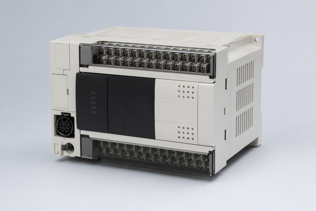
Industrial automation has changed the way modern machines are designed, operated, and monitored. At the center of many small and medium-sized control systems, the Mitsubishi FX Series PLC provides a practical way to manage motors, sensors, valves, switches, conveyors, and many other industrial devices. Its compact design, reliable operation, and flexible programming options have made the FX family a familiar choice for machine builders, technicians, and automation professionals.
A programmable logic controller, commonly called a PLC, works as the control unit of an automated machine. It receives information from input devices, processes that information according to a programmed logic, and then controls output devices. In simple terms, the PLC continuously checks what is happening in a machine and decides what should happen next.
The Mitsubishi FX family has remained popular because it combines useful control features with a compact form factor. Therefore, it can fit into control panels where space is limited while still handling a wide range of automation tasks. For beginners, it also provides a practical way to understand PLC programming and industrial control without starting with an overly complicated system.
What Is a Mitsubishi FX Series PLC?
A Mitsubishi FX Series PLC is a programmable logic controller developed for controlling machines and automated processes. It receives information from input devices, processes that information according to a programmed logic, and then produces output signals to control connected equipment.
In a typical industrial machine, sensors may be used to detect position, temperature, pressure, level, or the presence of an object. These signals are received by the PLC. Afterward, the programmed instructions are processed by the controller. As a result, outputs can be activated to operate motors, valves, contactors, lamps, relays, or other industrial devices.
Because the control logic is stored inside the PLC, changes can usually be made through programming instead of physically rewiring the entire control system. Therefore, machine modifications can be performed more efficiently.
The Mitsubishi FX Series PLC is especially associated with compact machine-control applications. Its compact design allows it to be installed where panel space is limited. At the same time, different models and expansion options have been provided so that the controller can be adapted to different automation requirements.
Mitsubishi FX Series PLC Family
The FX family includes several generations and model ranges. Although the exact capabilities differ from one model to another, the overall purpose remains the same: provide dependable control for industrial machines and automated processes.
Older FX models helped establish the series as a widely used compact PLC platform. Later generations introduced improved processing performance, larger programming capabilities, better communications, and additional motion and positioning functions.
The FX3U became especially well known in industrial automation because it offered a strong balance between compact hardware and useful control functions. It can be found in applications such as packaging machines, conveyors, material-handling systems, pump control, and general-purpose machine automation.
More recent controllers, such as the FX5U, belong to the iQ-F generation. These PLCs provide modern programming and communication capabilities while maintaining the compact style associated with the FX family. Consequently, they are suitable for applications that require more advanced control but still need a relatively small controller.
Understanding the differences between generations is important before selecting hardware. A machine that only needs basic digital input and output control does not necessarily require the newest and most powerful model. On the other hand, an application involving networking, positioning, analog signals, or more advanced machine coordination may benefit from a newer controller.
How a Mitsubishi FX Series PLC Works
The basic working principle of an FX PLC follows the standard PLC scan cycle. First, the controller reads the signals connected to its inputs. These signals may come from switches, sensors, or other field devices.
Next, the CPU processes the programmed logic. During this stage, the PLC checks conditions in the program and determines which outputs should change state. Finally, the controller updates the outputs according to the results of the program.
This cycle happens continuously while the PLC is running. Therefore, a sensor state can influence an output within a very short period, depending on the controller, program structure, and application.
Consider a simple conveyor system. A start push button may provide a signal to one input. When the operator presses the button, the PLC detects the input and checks whether all required conditions are satisfied. If the safety and operating conditions are correct, the program can energize an output connected to a motor contactor. The conveyor then starts moving.
Now imagine that a proximity sensor detects an object at a specific location. The PLC can use that signal to stop the conveyor, activate a pneumatic cylinder, count the product, or perform another programmed action. In this way, the PLC coordinates different machine operations through logic rather than relying on direct manual control.
Main Components of an FX PLC System
An FX PLC system contains several important components, and each component performs a specific job. The CPU controls the main operation because it runs the user program and manages the entire control process.
The input section receives signals from external devices such as push buttons, proximity sensors, limit switches, and selector switches. These devices tell the PLC what is happening in the machine.
The output section sends control signals to external equipment. Depending on the application, outputs can control contactors, relays, indicator lamps, solenoid valves, and other devices.
The power supply provides the electrical power that the PLC needs to operate. Before installation, always check the required voltage and power specifications for the selected FX model.
The communication interface allows the PLC to exchange data with other industrial devices. For example, an FX PLC can communicate with an HMI, inverter, drive, or another controller when the selected model supports the required communication method.
Expansion modules add extra capabilities when the basic PLC configuration does not provide enough inputs, outputs, or special functions. These modules can help a system handle additional signals or specific control requirements.
Each component works together as part of one control system. The inputs collect machine information, the CPU processes the logic, and the outputs control the connected equipment. This simple relationship forms the foundation of many automated machines.
Mitsubishi FX Series PLC Programming Basics
Mitsubishi FX Series PLC programming provides a practical way to control machines, motors, sensors, valves, and many other industrial devices. In addition, Mitsubishi FX Series PLC systems give beginners a straightforward environment for learning ladder logic and machine control.
First, the PLC receives signals from connected input devices. Then, the Mitsubishi FX Series PLC processes those signals according to the program stored in its memory. After that, the CPU updates the output devices based on the logic conditions.
For example, a push button can provide an input signal to the Mitsubishi FX Series PLC. The PLC can then check the condition and activate a motor through an output. As a result, the machine performs the required operation automatically.
Moreover, ladder logic makes Mitsubishi FX Series PLC programming easier to understand because the program resembles traditional electrical control circuits. Therefore, beginners can gradually move from simple ON/OFF control toward more advanced automation tasks.
Mitsubishi FX Series PLC Ladder Logic
Ladder logic plays an important role in Mitsubishi FX Series PLC control systems. In particular, ladder logic allows engineers to create logical relationships between inputs, internal devices, timers, counters, and outputs.
For instance, a simple Mitsubishi FX Series PLC program can monitor a start button and a stop button. When the operator presses the start button, the PLC checks the required conditions. If every condition remains valid, the PLC turns on the motor output.
However, the control logic can become more advanced as the machine grows. Therefore, Mitsubishi FX Series PLC programming can include timers, counters, comparison functions, data registers, and internal relays.
Furthermore, programmers can divide complex machine operations into smaller logical sections. As a result, Mitsubishi FX Series PLC programs become easier to understand, test, and troubleshoot.
Mitsubishi FX Series PLC Inputs and Outputs
Inputs and outputs form the connection between the Mitsubishi FX Series PLC and the physical machine. Inputs allow the PLC to monitor external conditions, while outputs allow the PLC to control connected equipment.
For example, common input devices include push buttons, selector switches, proximity sensors, photoelectric sensors, and level switches. On the other hand, outputs can operate contactors, relays, solenoid valves, indicator lamps, and other control devices.
In addition, the Mitsubishi FX Series PLC continuously scans its input conditions, executes the control program, and updates its outputs. Therefore, the PLC can react to machine conditions without requiring constant manual operation.
The exact input and output configuration depends on the Mitsubishi FX Series PLC model. Consequently, engineers should always check the electrical specifications of the selected PLC before connecting field devices.
Mitsubishi FX Series PLC Timers and Counters
Timers and counters add useful control functions to an FX Series PLC. A timer can create a controlled delay, while a counter can track how many times an event occurs. Therefore, these functions help programmers build more practical automation sequences without adding unnecessary hardware.
For example, imagine a conveyor that should continue running for five seconds after a sensor detects a product. In this situation, a timer can maintain the required output for the selected period. As a result, the machine can complete the movement without requiring a separate timing device.
Counters work in a similar way, but they focus on repeated events. For instance, a sensor can detect every product that passes through a production line. The controller can then increase the counter value after each detection. Once the counter reaches its preset value, the program can start another operation.
Moreover, timers and counters can work together. A packaging machine, for example, may count a specific number of products and then wait for a short delay before activating a sealing mechanism. Consequently, these simple functions can support surprisingly useful machine sequences.
Mitsubishi FX Series PLC Internal Devices
Internal devices allow the controller to manage information without connecting every condition to a physical input or output. These devices can help programmers create cleaner and more organized ladder programs.
For example, internal relays can represent machine states, temporary conditions, or control steps. Instead of repeating the same input condition across several program sections, a programmer can use an internal device and reference it where needed.
In addition, data registers can store numerical values used by the control program. These values may represent counters, settings, process values, or other application data. Therefore, internal devices can make larger control programs easier to structure.
When programmers organize these devices carefully, the overall logic becomes easier to understand. Furthermore, clear device management reduces the chance of address conflicts and programming mistakes.
Mitsubishi FX Series PLC Analog Control
Digital signals work well for many basic machines, but some applications require variable values. Temperature, pressure, speed, level, and flow can all change gradually rather than simply switching between ON and OFF.
For these applications, an FX Series controller can work with suitable analog hardware when the selected configuration supports it. An analog input module can provide a numerical value that the program can process.
For example, a pressure sensor may provide a changing signal as system pressure rises or falls. The PLC can read that value, compare it with predefined limits, and then control another device according to the result.
Moreover, the program can convert raw input values into useful engineering information. Therefore, operators can work with values that make sense for the machine rather than dealing only with raw electrical readings.
Mitsubishi FX Series PLC Data Registers
Data handling becomes increasingly important as automation projects become more advanced. Data registers allow the program to store numerical information and use that information during operation.
For example, a machine may need to remember production counts, timing values, setpoints, or operator-adjustable parameters. The controller can store these values and use them when the logic runs.
In addition, programmers can compare stored values with current process information. Suppose a production counter reaches a target quantity. The program can detect that condition and move the machine to the next step.
Furthermore, organized data management makes troubleshooting easier. When technicians understand what each register represents, they can inspect important values more quickly and identify unusual conditions.
Mitsubishi FX Series PLC Program Structure
A well-structured program makes automation projects easier to maintain. Instead of placing every instruction into one large section, programmers can organize the logic around machine functions.
For example, one section can handle startup conditions, another can control manual operation, and another can manage automatic sequences. Alarm handling and auxiliary functions can also use separate logical areas.
As a result, technicians can locate specific control functions more quickly. Moreover, a structured program reduces confusion when someone needs to modify the system later.
Before writing the complete application, it also helps to create a simple machine sequence on paper. This approach allows the programmer to identify inputs, outputs, interlocks, timers, counters, and operating steps before entering the ladder logic.
Mitsubishi FX Series PLC Safety Considerations
Safety deserves careful attention in every industrial automation project. A programmable controller can manage machine logic, but engineers should not treat ordinary control logic as a replacement for dedicated safety equipment.
For example, emergency-stop circuits, protective devices, safety switches, and other safety-related functions may require separate safety hardware depending on the application and applicable standards.
Therefore, engineers should design the machine safety system independently and integrate control functions appropriately. The exact requirements depend on the equipment, environment, risk level, and local regulations.
In addition, technicians should never test an unfamiliar machine without understanding its hazards. Proper isolation, electrical protection, and safe testing procedures remain essential during installation and maintenance.
Mitsubishi FX Series PLC Communication With HMIs and Drives
Modern machines often contain several intelligent devices, and communication allows those devices to exchange useful information. An FX Series system can connect with compatible HMIs, drives, and other equipment when the required interfaces and protocols are available.
For instance, an HMI can display motor status, alarm conditions, production data, and operator settings. Meanwhile, a drive can receive speed-related commands while sending operating information back to the controller.
As a result, the automation system can coordinate multiple devices through a central control strategy. Furthermore, communication reduces the need for large amounts of point-to-point wiring in applications that support networked devices.
However, the exact communication method depends on the PLC model, communication hardware, and connected equipment. Therefore, engineers should verify compatibility before designing the final network.
Mitsubishi FX Series PLC Online Monitoring
Online monitoring helps programmers understand what the controller is doing while the machine operates. Instead of guessing why an output remains OFF, a technician can inspect the ladder logic and observe which conditions are currently true.
For example, if a motor does not start, the programmer can follow the logic from the start command through the required interlocks. If one condition remains false, the program can reveal where the sequence stops.
Moreover, monitoring helps during commissioning because programmers can verify sensor responses, timers, counters, and internal states in real time. Consequently, faults become easier to locate.
However, live machine monitoring requires caution. Technicians should always follow safe operating procedures and avoid making uncontrolled changes while equipment is moving.
Mitsubishi FX Series PLC Error Diagnosis
Error diagnosis becomes much easier when technicians follow a logical process. First, check the controller status and determine whether the issue affects the PLC itself or the connected machine.
Next, inspect the input signals. If a sensor should produce a signal but the PLC does not detect it, investigate the sensor, wiring, power supply, and connection points.
After that, examine the output side. If the program activates an output but the field device does not respond, the problem may exist in the wiring, relay, contactor, actuator, or power circuit.
In addition, review recent program changes. A machine may develop a problem after someone modifies a sequence, changes an address, or adjusts a timer value.
Therefore, troubleshooting should move from simple checks toward deeper software analysis. This method saves time and helps technicians avoid unnecessary changes.
Mitsubishi FX Series PLC Installation Practices
A successful installation starts with the control panel design. The PLC, power supply, terminal blocks, communication equipment, and other components should have enough space for safe wiring and future maintenance.
Moreover, technicians should keep signal wiring organized and clearly identified. Proper labeling makes future troubleshooting much faster.
Electrical noise also deserves attention, especially near motors, contactors, and variable frequency drives. Good panel design, suitable grounding, proper cable routing, and appropriate protection can help reduce unwanted interference.
Furthermore, the installation environment matters. Temperature, humidity, dust, vibration, and other conditions can affect electronic equipment. Therefore, the selected hardware should match the actual operating environment.
Mitsubishi FX Series PLC Project Testing
Testing should begin before the complete machine enters production. Programmers can first verify basic inputs and outputs, then move toward individual sequences and finally test the complete process.
For example, a conveyor application may start with sensor verification. After that, the programmer can test motor commands, timing functions, counters, alarms, and automatic sequences.
In addition, unusual conditions should receive attention. A good test does not only confirm that the machine works normally. It also checks what happens when a sensor fails, a stop command activates, a timer expires unexpectedly, or an operator enters an incorrect condition.
As a result, structured testing can reveal problems before they create production downtime.
Mitsubishi FX Series PLC Maintenance and Backup
Regular maintenance can extend the useful life of an automation system. Technicians should inspect the panel, review connections, check unusual temperatures, and investigate repeated alarms.
Most importantly, keep a reliable backup of the working PLC program. Losing the original application can create significant downtime when a controller or memory device fails.
Furthermore, store documentation alongside the backup where practical. I/O information, wiring diagrams, parameter settings, and communication details can help technicians restore the system more efficiently.
Therefore, maintenance should cover both hardware and software. A healthy control panel with no current alarms can still become difficult to repair if the original program and documentation are missing.
Mitsubishi FX Series PLC Selection Guide
Choosing the correct controller requires more than counting inputs and outputs. The application may also require analog signals, high-speed functions, communication features, expansion options, or specific processing capabilities.
First, determine how many inputs and outputs the machine needs. Next, identify whether those signals are digital or analog. After that, consider communication requirements and future expansion.
Moreover, think about the machine's operating sequence. A simple control task may need only basic logic, while a more demanding application may require faster processing and additional modules.
Finally, compare the selected model against the actual project requirements rather than choosing hardware based only on price. As a result, the control system is more likely to provide reliable performance and useful expansion options.
Mitsubishi FX Series PLC vs Other Compact PLCs
Compact PLCs from different manufacturers can perform similar control tasks, but each product family has its own programming environment, hardware options, and communication features.
The FX Series remains popular for machine-control applications because it can provide a compact solution for projects that do not require a very large controller architecture.
However, another PLC family may suit a particular application better when it requires different networking options, specialized functions, or a larger expansion structure.
Therefore, engineers should compare controllers based on the actual application. I/O capacity, programming software, communication, expansion, maintenance, and long-term availability can all influence the final decision.
Mitsubishi FX Series PLC Beginner Project Ideas
Beginners can learn faster by building small projects instead of jumping directly into complicated machines. A simple motor start-stop circuit can teach basic inputs, outputs, latching logic, and interlocking.
Next, a traffic-light project can introduce timers and sequential logic. After that, a conveyor simulation can combine sensors, motor control, counters, and timing functions.
Furthermore, a tank-level project can introduce multiple sensors and automatic pump control. As experience grows, learners can combine several functions into one complete sequence.
These projects provide practical experience and help beginners understand how ladder logic connects software instructions with real machine behavior.
Frequently Asked Questions About Mitsubishi FX Series PLC
What can a Mitsubishi FX Series PLC control?
An FX Series PLC can control many machine functions, including motors, valves, indicators, conveyors, pumps, sensors, and other compatible automation devices.
Can beginners learn Mitsubishi FX Series PLC programming?
Yes. Beginners can start with basic ladder logic and gradually learn inputs, outputs, timers, counters, internal devices, data handling, and communication.
Why are timers important in Mitsubishi FX Series PLC programs?
Timers allow programmers to introduce controlled delays and timed operations. Therefore, they help machines perform tasks in the correct order.
What do counters do in Mitsubishi FX Series PLC systems?
Counters track repeated events such as product detection, machine cycles, or completed operations. Once the selected count reaches its target, the program can trigger another action.
Can this PLC system work with an HMI?
Compatible configurations can connect the controller with an HMI. This arrangement allows operators to monitor machine conditions and interact with selected control functions.
How should beginners troubleshoot an FX Series PLC system?
Beginners should start with basic checks such as power, input signals, output conditions, wiring, and program logic. Then, they can move toward deeper diagnosis when the basic checks do not reveal the problem.
Is documentation important for Mitsubishi FX Series PLC projects?
Yes. Clear documentation helps technicians understand wiring, I/O assignments, program structure, communication settings, and maintenance procedures. Consequently, it can reduce downtime during future repairs.
Conclusion
The Mitsubishi FX Series PLC provides a practical platform for learning and applying programmable control in many machine-automation projects. Its combination of ladder logic, timers, counters, internal devices, data handling, and communication features gives engineers the tools needed for a wide range of control tasks.
Moreover, beginners can build their skills through small projects and gradually move toward more advanced applications. By learning how inputs, outputs, logic, timing, counting, communication, and troubleshooting work together, they can create more reliable automation programs.
At the same time, successful PLC control depends on more than programming alone. Proper hardware selection, safe installation, structured testing, good documentation, and regular maintenance all contribute to a dependable automation system.
Finally, the best way to understand an FX Series PLC is to combine theory with practical exercises. Start with simple control logic, test every function carefully, and gradually increase the complexity of each project. This approach creates a stronger foundation for real-world industrial automation.